29
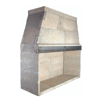
Step 13: Cut one end of the other two smoke dome top big, part
13, components at an angle parallel to the opposite end of the
piece. The bottom length of the cut piece should measure
35 3/4” (Figure 59).
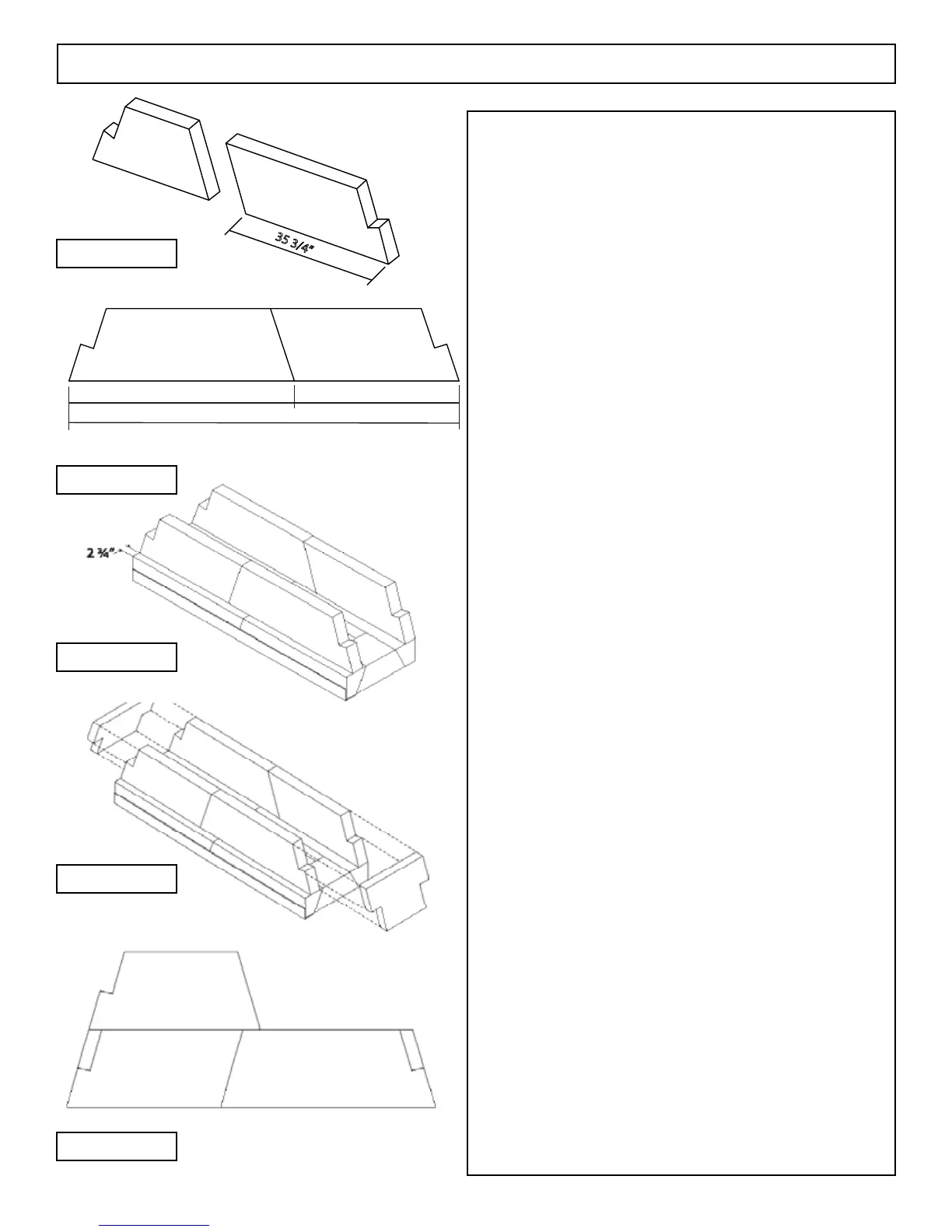
Step 14: Place one modied smoke dome top big pieces (haunch
cut off and a bottom length of 49 3/4” together with one of the
smoke dome top big pieces that was angle cut to 35 3/4” bottom
length and parallel angle) together on the damper support and
ush with the back wall of the rebox so that the two smoke
dome pieces meet along their eld modied cut line (Figure 60).
The overall length of the two joined smoke dome
pieces should be 85 1/2”.
Step 15: Repeat Step 14 on the front damper support. Set the
front smoke dome components 2-3/4” back from the front face
of the front damper support (Figure 61).
Step 16: Fit the top sloping smoke dome side wall components,
part 34, in place between the front and back smoke dome ar-
rangements at each end of the smoke dome (Figure 62).
Step 17: Place one of the four modied smoke dome top big
pieces (haunch cut off and 49 3/4” bottom length) on top of and
ush with the rst tier of smoke dome components at the back of
the rst course of smoke dome.
The haunched, un-cut end of this piece should be ush
with the haunch end of the rst tier smoke dome below it
(Figure 63).
Step 18: Repeat this arrangement at the front of the smoke
dome.
Step 19: Cut each of the two smoke dome top medium
pieces, part 11 at an angle cut that is parallel to the un-cut end
and so that its bottom length is 25 1/2” (Figure 65).
Step 20: Place one of the angle cut smoke dome top medium
pieces at the front and one at the back of the rst tier smoke
dome so that they meet the smoke dome top big (haunch cut
off and 50” bottom length) already set in Steps 14 and 15. The
overall width dimension at the top of the smoke dome should be
65-1/2” (Figure 66).
Step 21: Fit the top sloping smoke dome side wall components,
part 34, in place between the front and back smoke dome ar-
rangements at each end of the smoke dome (Figure 67).
Assembly Instructions - 72” (cont.)
FIGURE 59
FIGURE 60
FIGURE 61
FIGURE 62
FIGURE 63
 Loading...


