pg. 4
Connecting the Power
1. Once a location has been selected for the I600 unit, use the provided template to cut a hole in the wall. Should
be approximately 50” above the floor. (5 1/2” Tall and 10” Wide).
2. Run a dedicated power to the location of I600 unit. The power supply on the I600 unit can automatically
detect the voltage applied directly to the unit. This means 110V or 220V can be used to power the system.
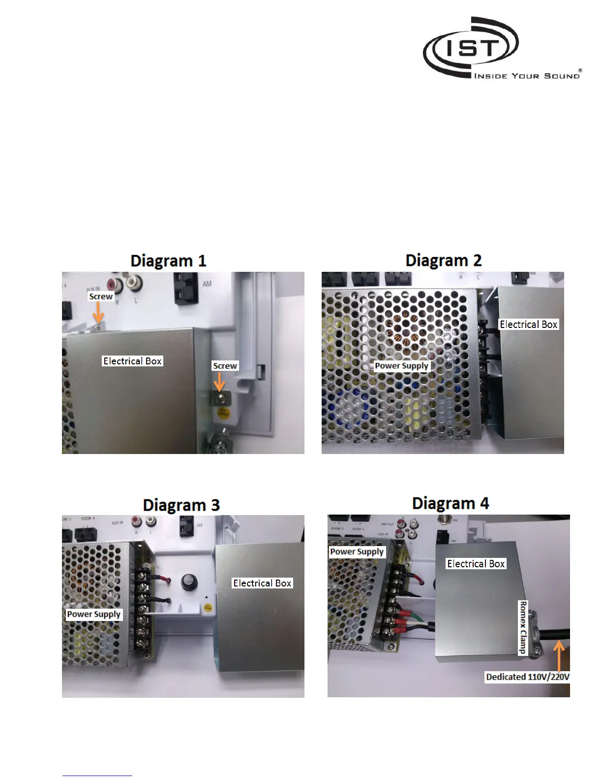
3. Once you are ready to apply power to the I600 unit, remove the screws that secure the electrical box to the
I600 unit. Refer to “Diagram 1”
4. Slide the electrical box shown on Diagram 2 and Diagram 3 so the power connections are exposed.
5. Feed the power through the Romex clamp on the electrical box show on Diagram 4
6. Attach the power to the bottom three screws of the power supply show on Diagram 4.
7. Use the Romex clamp to secure the power in place.
8. Slide the electrical box back onto the power supply and line up the holes. Use the screws to secure the
electrical box back in place. Refer to Diagram 1.
 Loading...