(2) How to Read the Explanations
An exploded view, sectional views, a system diagram, etc. are shown at the beginning of each
section as required for easy understanding of the mounted states of the components.
For the removal/installation of each part, the procedure is shown with the procedural step No. in the
illustration.
Precautions and key points for disassembly and reassembly of parts are described as points. In
the explanation for each point, detailed operation method, information, standard and precautions
are described.
Description Example
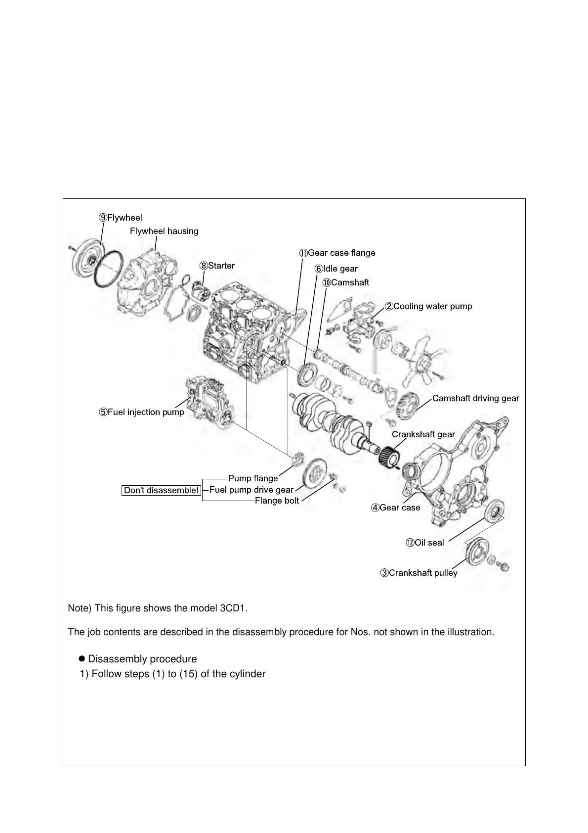
Cooling water pump
Camshaft
Gear case flange
Flywheel
Starter
Flywheel hausing
Idle gear
Gear case
Oil seal
Crankshaft pulley
Crankshaft gear
Camshaft driving gear
Fuel injection pump
Fuel pump drive gear
Flange bolt
Don't disassemble!
Pump flange
Note) This figure shows the model 3CD1.
The job contents are described in the disassembly procedure for Nos. not shown in the illustration.
Disassembly procedure
1) Follow steps (1) to (15) of the cylinder head disassembly procedure.
2) Remove the cooling water pump.
3) Remove the crankshaft pulley. (Point 1) ← Operation point to be explained on a later page.
Operation points
Disassemble: Service point for removal
Reassemble: Service point for installation
Disassemble-Reassemble: Service point required in both removal and installation.