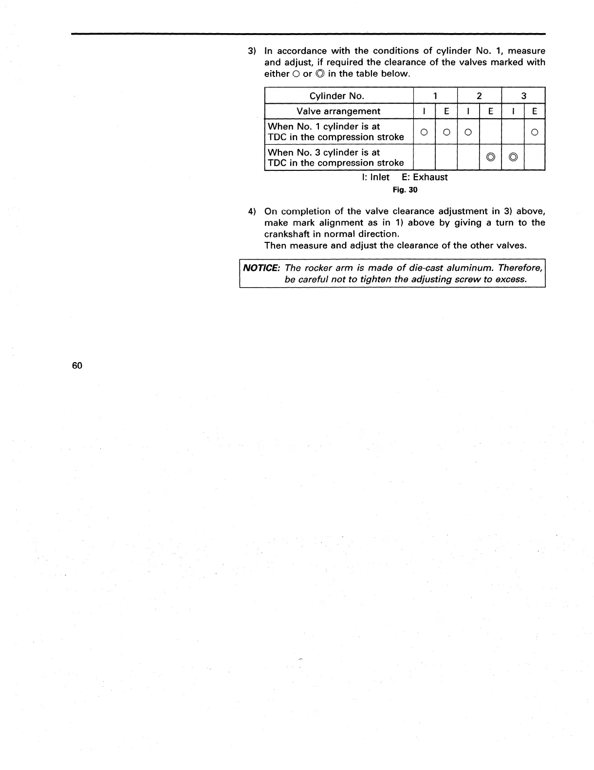
3) In accordance with the conditions of cylinder No. 1, measure
and adjust, if required the clearance of the valves marked with
either
0
or 0 in the table below.
I
Cylinder No.
I
1
I
2
I
3
I
I
Valve arrangement
I’IEI’IEI ‘Id
TDC in the compression stroke
l”lolol I loI
When No. 1 cylinder is at
TDC in the compression stroke
I I I l”lol I
When No. 3 cylinder is at
I: Inlet E: Exhaust
Fig. 30
4)
On completion of the valve clearance adjustment in 3) above,
make mark alignment as in 1) above by giving a turn to the
crankshaft in normal direction.
Then measure and adjust the clearance of the other valves.
be careful not to tighten the adjusting screw to excess.
60