USE ONLY WITHA 250V FUSE
12
3
12
3
MUTE
+
MIC 2
XLR
GAIN
MIC 2
+48V
PHANTOM
MIC2
MIC3
MIC 2
MIC 3
MIC 3
+48V
PHANTOM
AUX2
INPUT
MIX
OUT
AUX1
INPUT
MIC2
MIC3
LINE INPUT
MIC 3
XLR
GAIN
EMC INPUT
70V
COM 4-16 100V
OUTPUT
COM COM
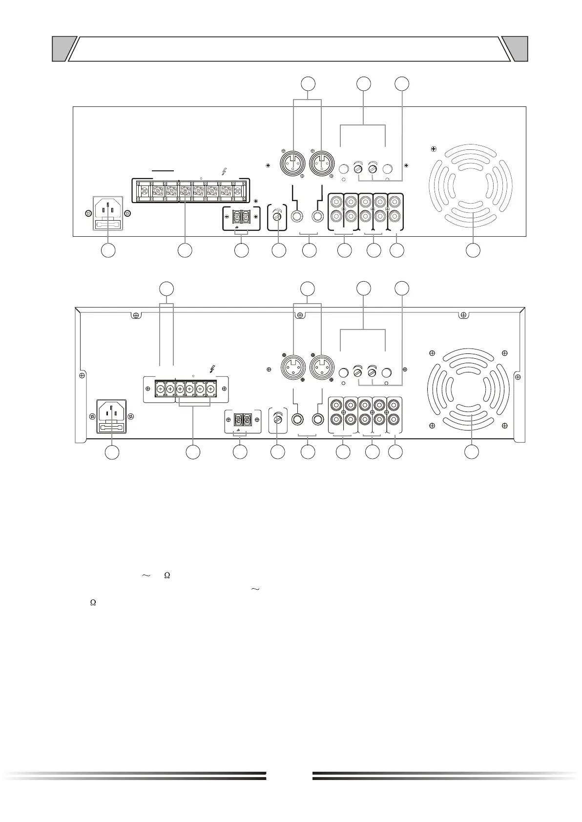
NOMENCLATURE AND FUCTIONS
12
14
15 1918 2013 1716
23
9
USE ONLY WITHA 250V FUSE
12
3
12
3
MUTE
+
MIC 2
XLR
GAIN
MIC 2
+48V
PHANTOM
MIC2
MIC3
MIC 2
MIC 3
MIC 3
+48V
PHANTOM
AUX2
INPUT
MIX
OUT
AUX1
INPUT
MIC2
MIC3
LINE INPUT
MIC 3
XLR
GAIN
EMC INPUT
COM 4-16 70V 100V
OUTPUT
DC 24V
-
+
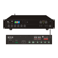
4.5 T-350B-550B-650B REAR PANEL(3U)
4.6 T-350B-550B-650B REAR PANEL+24V(3U)
24 23
12. ~220-240V 50/60Hz AC POWER INPUT
(Specific voltage and frequency values to
the machine to prevail in kind.)
SPEAKER TERMINALS
14. EMC
15. MUTE
13.
Connecting the speaker terminal. COM is
for public terminal which could be
connected with negative terminal and the
ground wire. 4 16 terminal is used to
connect the speaker with impedance 4
16 ; 70V terminal is used to connect the
speaker with 70V; 100V terminal is used
to connect the speaker with 100V.
Once there is signal to the emergency
alarm signal input, the equipment will play
the music signal in this channel as priority
except MIC1.
When turning the mute potentiometer to
the right, it is at the maximum mute;
whereas it is the minimum.
16. MIC2\MIC3
MIC Unbalanced inputs.
17. MIC2 LINE/MIC3 LINE
MIC2/MIC3
18. AUX1/AUX2
19. MIX OUT
20.
.
line un-balanced input.
Aux input jack, un-balanced connecting
terminal.
Mixed output is used to connect the next
equipment.
VENTILATION
it is for cooling purpose. Pls keep it open
when it is working to avoid overheating.
21. GAIN CONTROL
to adjust the mic gain
22. PHANTOM POWER SWITCH
The power choice of XLR mic input.
23. MIC2/MIC3
XLR input terminal
24 SPARED (BATTERY) POWER INTERFACE.
12
14
15 1918 20
13
1716
22 21
22 21