Function and Features
Copyright ©ITECH Electronic Co., Ltd. 31
The above parameters can be selected through the configuration menu. Press the
+ (Menu) to enter the menu. Press the Right Key to select CONFIG and press
to enter the configuration menu; press the Right Key to select the Ext-Ctrl and
press to enter the configuration of external analog quantity parameters.
When setting every item, please coordinate the Up/Down Key for selection.
For example, if 0-10V external analog is applied for control and internal 5V voltage is
adopted for monitoring the front board output, slections will be made as below:
5v-M 10v/10k-P V-P On
After selecting the Ext-Ctrl as “On”, exit the Menu. At this time, the Rear indicator on the
VFD status bar will be lighted on and the right corner will display “Analog”.
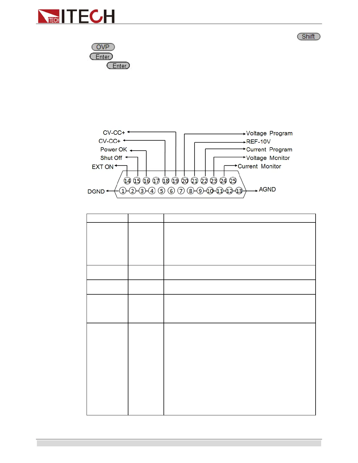
DB-25
14
EXT ON
Used for controlling the ON/OFF of the power supply.
When Pin 1 is connected to Pin 14,
supports the output disable function; in case of high level,
the output is controlled by On/Off; in case of low level, the
output is disabled. This function is invalid under on-line
status.
Used for switching off the function under emergency
status (in normal circumstances, the pin is not used).
Used for indicating whether the power output is normal; if
so, output 5V; in case of power supply failure, output 0V.
Pin 19
CV_CC-
The output between these two pins is used for indicating
the working status of power supply; under CV mode, the
output between these two pins is 5V; and under CC mode,
- 5V.
Program
(Voltage
setting)
Output voltage of analog quantity control:
In setting the V-PRG and 10v/10k-
quantity range should be 0-10V voltage, and the regulated
output voltage should be from 0 to full range;
In setting the V-PRG and 5v/5k-
quantity range should be 0-5V voltage, and the regulated
output voltage should be from 0 to full range;
In setting the R-PRG and 10v/10k-
quantity range should be 0-
regulated output voltage should be from 0 to full range;
In setting the R-PRG and 5v/5k-P, the
quantity range should be 0-
5K resistance, and the
regulated output voltage should be from 0 to full range;