EasyManua.ls Logo

ITech IT8513C+ User Manual

ITech IT8513C+
80 pages
To Next Page IconTo Next Page
To Previous Page IconTo Previous Page
Page #55 background imageLoading...
Page #55 background image
Automatic Test Function
Copyright © Itech Electronic Co., Ltd. 46
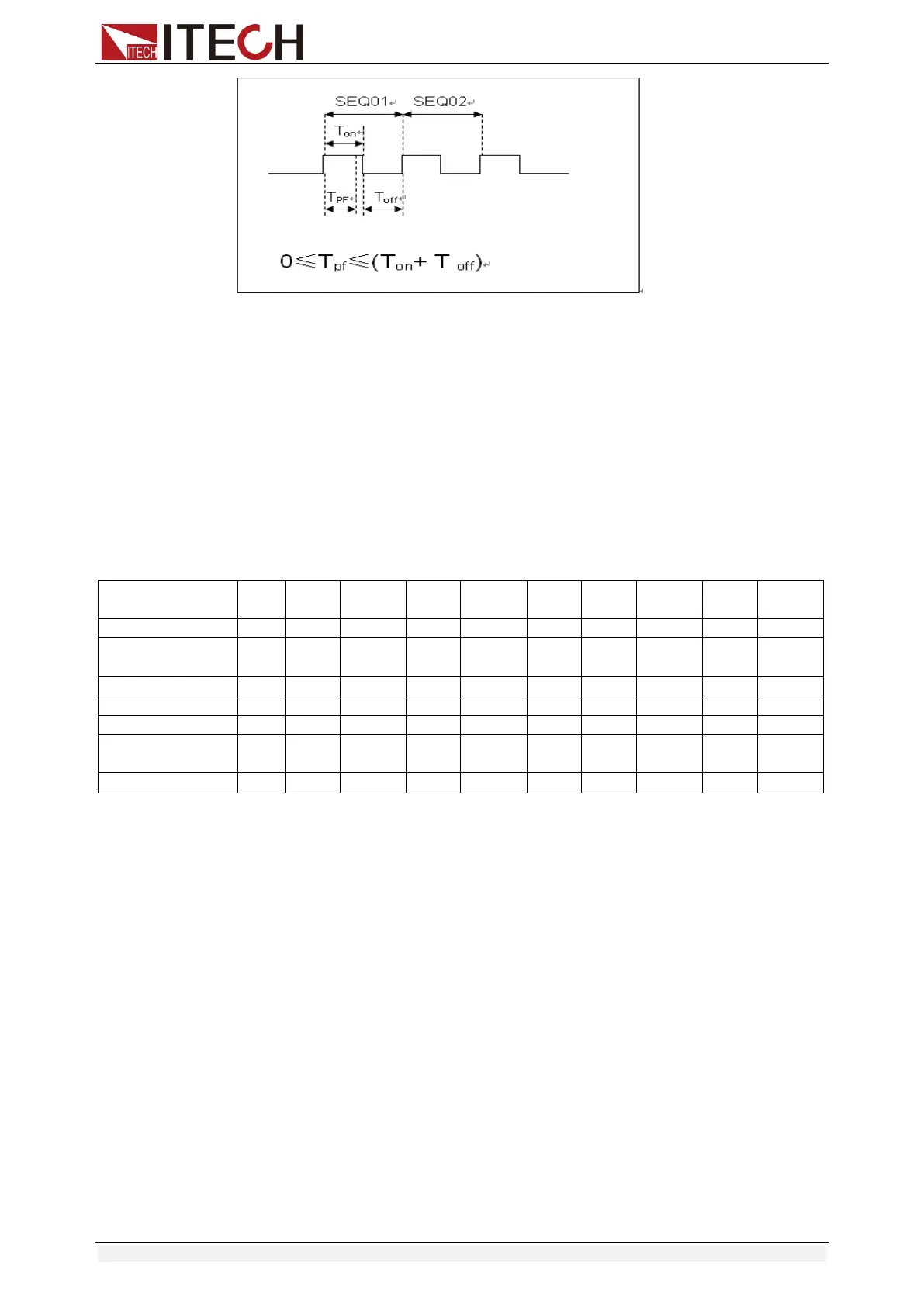
Tpf is the delay time for a step.
12. Set stop conditions: COMP means stop test when all the steps are
completed, FAILURE means stop test when the testing fails. Press [Enter]
key to confirm.
STOP COMP FAILURE
13. Select the test file to link if you’d like to. The linked file must be saved
before. 0 stands for not linking to other files. Press [Enter] key to confirm.
CHAIN PROGRAM=0 (0-10)
Automatic test file and single step storage correspondence table
PROGRAM 1
Sequence
1
2
3
4
5
6
7
8
9
10
Save Group
1
2
3
4
5
6
7
8
9
10
PROGRAM 2
Sequence
1
2
3
4
5
6
7
8
9
10
Save Group
11
12
13
14
15
16
17
18
19
20
:
:
PROGRAM 10
Sequence
1
2
3
4
5
6
7
8
9
10
Save Group
91
92
93
94
95
96
97
98
99
100
14. Save the edited files in EEPROM, you can save up to 10 groups of files, e.g.
please press [1] to save the edited file in group 1, and then press [Enter] to
confirm.
SAVE PROGRAM =1 (1-10)
The above is the automatic test structure. The automatic test single step
specific settings also need to be edited separately, so the design is to
facilitate the modification of the single step settings.
10.0000V 0.0000A
0.00W I=1.000A
15. Select an operation mode and then press [Shift]+[CV] (Setup) to set
related parameters.
16. Edit the automatic test single step, details refer to below procedure.
After all the steps are set, press [Shift]+[4] (save) to save.
Set the steps of a test file in the example
In the above step 16, assume that the first step is edited to CC mode, current
2A, the upper limit voltage value is 10V, the lower limit voltage value is 2V; the
second step is edited to CV mode, voltage 3V, upper limit current value 5A,
lower limit current value 0A. Save in the automatic test file 2.

Table of Contents

Other manuals for ITech IT8513C+

Question and Answer IconNeed help?

Do you have a question about the ITech IT8513C+ and is the answer not in the manual?

ITech IT8513C+ Specifications

General IconGeneral
BrandITech
ModelIT8513C+
CategoryTest Equipment
LanguageEnglish

Summary

Safety Notices

CAUTION

Denotes a hazard, requires correct performance to avoid damage or data loss.

WARNING

Denotes a hazard, requires correct performance to avoid injury or death.

NOTE

Denotes important hints, tips, or supplementary information.

Quality Certification and Assurance

Warranty

Limitation of Warranty

Conditions invalidating the warranty, e.g., damage, unauthorized modification.

Safety Precautions

WARNING

Lists critical safety warnings for operation, e.g., voltage, damage, grounding.

CAUTION

Lists cautions for instrument usage, e.g., cleaning, vent holes.

Environmental Conditions

Regulatory Markings

CE

Indicates compliance with relevant European legal directives.

WEEE Directive Symbol

Symbol indicating safe period for hazardous substance use and recycling.

Compliance Information

EMC Standard

Lists EMC standards and reference standards the product conforms to.

Safety Standard

Lists safety standards the product conforms to.

Chapter1 Inspection and Installation

1.1 Verifying the Shipment

Instructions for unpacking and checking instrument contents against package list.

1.6 Connect the Power Cord

Precautions and steps for connecting the power cord safely.

1.7 Connect the Device Under Test (DUT)

Precautions and steps for connecting the device under test.

Optional Accessories

1.2 Instrument Size Introduction

1.3 Adjustment of Load Handle

1.4 Disassembly of Load Handle

1.5 Rack Mounting

Remote Measurement

Chapter2 Quick Start

2.1 Brief Introduction

Overview of IT8500+ series loads and their applications.

2.2 Product Feature

Lists key features and capabilities of the IT8500+ series electronic loads.

2.3 Front Panel Introduction

2.4 Front Panel Keys

2.5 Combination Keys

2.6 VFD Annunciators

2.7 Rear Panel Introduction

2.8 Power-on Selftest

Exception Handling

Chapter3 Functions and Characteristics

3.1 Local Mode/Remote Mode

Explains how to switch between local and remote operation modes.

3.2 Operation Mode

Details the four main operation modes: CC, CV, CR, CW.

3.2.1 Constant Current Mode (CC)

Describes the Constant Current mode and setting the current value.

3.2.2 Constant Voltage Mode (CV)

3.2.3 Constant Resistance Mode (CR)

3.2.4 Constant Power Mode (CW)

3.3 Input On/Off Control

3.4 Key Lock Function

3.5 Short-circuit Analog Function

3.6 System Menu (System)

3.7 Config Menu (Config)

3.8 Trigger Function

3.9 LIST Operation

3.10 Test Function

3.10.1 Transient Test Function

Pulse Mode

Toggled Mode

3.10.2 OCP Test Function

3.10.3 OPP Test Function

3.10.4 Battery Discharge Test

Battery Test Data Recalling

3.10.5 CR-LED Test Function

3.10.6 Measurement of Voltage Rise Time

3.11 Saving and Recalling Settings

3.12 VON Function

3.13 Protection Function

3.14 Current Monitoring (I Monitor)

3.15 Ripple Function

Chapter4 Automatic Test Function

4.1 Introduction

Overview of automatic test editing modes and operation.

4.2 Automatic Test Mode Switching

How to switch between 'NEW' and '8500' automatic test modes.

4.2.1 Test Mode for IT8500+

4.2.2 Test Mode for IT8500

Chapter5 Specifications

Specifications (IT8511+)

Detailed specifications for IT8511+ model, including voltage, current, power, modes, and protection.

Specifications (IT8512+)

Detailed specifications for IT8512+ model, including voltage, current, power, modes, and protection.

Specifications (IT8511A+/IT8512A+)

Detailed specifications for IT8511A+ and IT8512A+ models.

Specifications (IT8511B+)

Detailed specifications for IT8511B+ model, including voltage, current, power, modes, and protection.

Specifications (IT8512B+)

Specifications (IT8512C+)

Supplementary Characteristics

Specifications (IT8512H+)

Specifications (IT8513A+)

Specifications (IT8513B+)

Specifications (IT8513C+)

Specifications (IT8514C+)

Specifications (IT8514B+)

Specifications (IT8516C+)

Chapter6 Communication Interfaces

6.1 Communication Modules Introduction

Introduction to communication modules like RS232, USB, and their compatibility.

IT-E122 Communication Module

IT-E121A Communication Module

6.2 Communication with PC

USB Interface

Appendix

Specifications of Red and Black Test Lines

Specifications of optional test lines and maximum current values.

Contact Us

Related product manuals