EasyManua.ls Logo

ITech IT8700 Series - Controlling Link

ITech IT8700 Series
90 pages
To Next Page IconTo Next Page
To Previous Page IconTo Previous Page
Loading...
Panel function introduction
Copyright © Itech Electronic Co., Ltd. 34
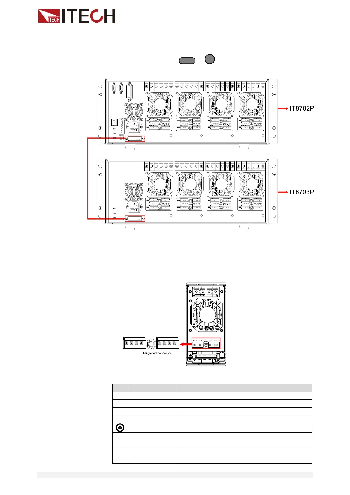
Procedure:
Take example of IT8702, use expanded cable to connect mainframe and
expand interface of extended frame. Enable expand function in the menu of
IT8702 mainframe by pressing + , select “Expand module”, choose
ON.
Figure 3-8 Expand connections
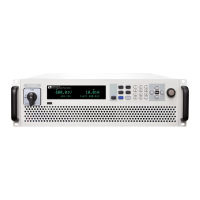
3.6 Controlling link
There is an 8-pin connector on every module’s rear panel. The following will
introduce in detail the 8 pins’ specific functions.
Fig 3-9 Terminals on single-channel module rear panel
No.
Pin
Description
1
GND
Ground
2
VF
Voltage fault indication terminal
3
DI
Digital input terminal
4
DO
Digital output terminal
I Monitor
Current monitoring output
5
Sense +
Voltage remote measuring terminal(+)
6
Sense -
Voltage remote measuring terminal(-)
7
Ext_PRG+
External analog controlling terminal(+)
8
Ext_PRG-
External analog controlling terminal(-)
ShiftShift
44

Table of Contents

Other manuals for ITech IT8700 Series

Related product manuals