SERVICE MANUAL
E-124
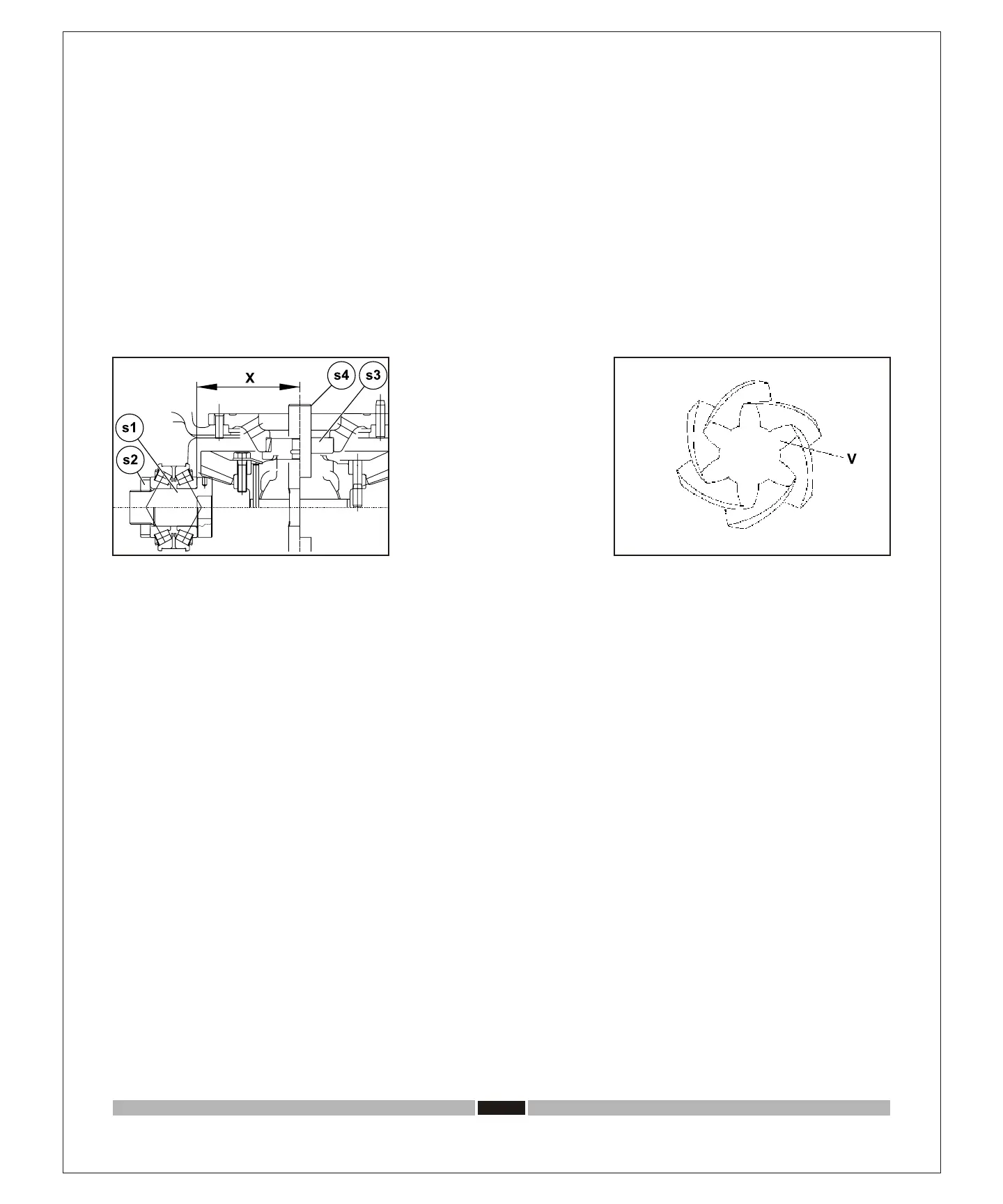
Fig.5
5. Insert false pinion (s1) with bearing cones (11) and (13) in the related housings then assemble nut ring (s2). Screw in without
exceeding nut ring (s2) till the end float is eliminated. Install false differential box (s3, s4).
See: fig.5.
6. Measure distance X (distance between the axis of the differential bearings and the base of pinion head) with a depth gauge.
See: fig.5.
7. In order to determine necessary thickness value (S) between pinion and bearing, subtract value (V), stamped on the pinion
head (V=requested distance), from the measured value (X).
S=X-V mm
Fig.6
ITL