IU_26779_1_ENG_MANUAL_SEMSC11 13 / 21
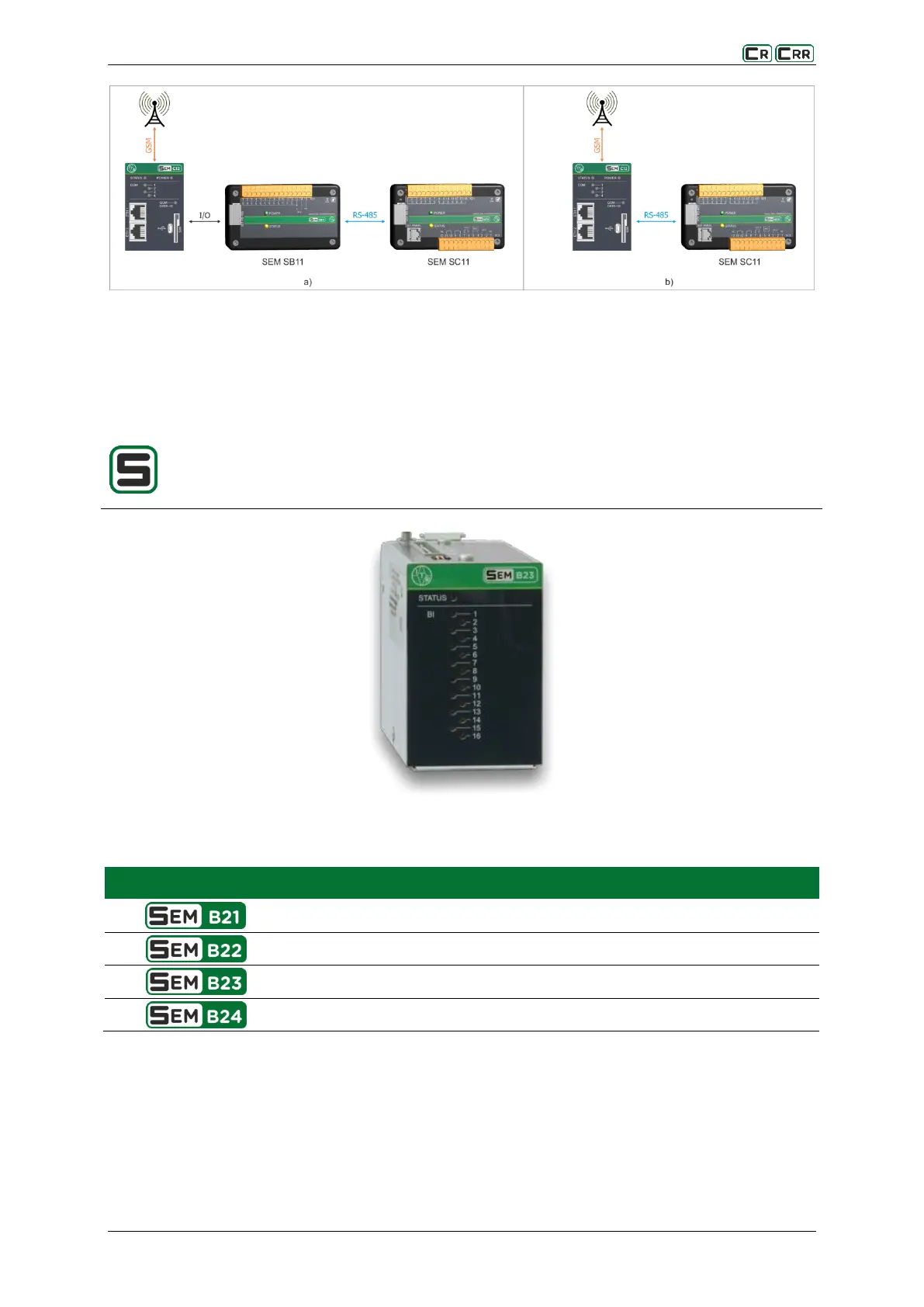
Fig. 3.6. Flowchart illustrating the interaction with the telemechanics
a) via binary inputs / outputs with the SEM SB11 module
B) via RS-485 link
3.3.3. SEM Bxx - binary inputs and outputs
SEM Bxx extends the system with binary inputs and outputs, their state is represented with
the LEDs located on the front panel. The readout and analysis of input and output states is done
using the main controller module SEM Cxx .
Fig. 3.7. Module SEM B23
Table 3.8. Comparison of the binary input and output module SEM Bxx
8 binary inputs and 8 binary outputs
16 binary inputs and 16 binary outputs