IU_26779_1_ENG_MANUAL_SEMSC11 9 / 21
Panels 3.2.
For local control of the device, PAN 1 or PAN 3 type detachable operator panels are used.
3.2.1. PAN 1
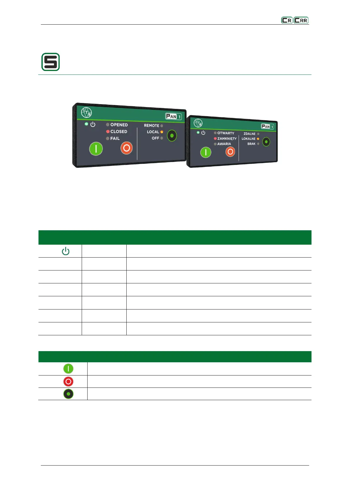
Fig. 3.2. View of the front panel PAN 1
The PAN1 panel is the smallest in the series of panel and is intended for mapping the status of the switches,
controlling the switches, and changing the control mode. The user interface consists of 7 signalling LEDs and
three buttons.
Table 3.2. Meaning of predefined diodes
Indicates that the correct supply voltage has been applied. Steady light.
Indicates an open connector. Steady light.
Indicates a closed connector. Steady light.
Indicates the connector failure status. Steady light.
Indicates the permission for the remote control. Steady light.
Indicates the permission for the local control. Steady light.
Indicates the lack of a permit to control. Steady light.
Table 3.3. The use of buttons
Control for the switch closing
Control for the switch opening
Change of the control location (local, remote, no control)