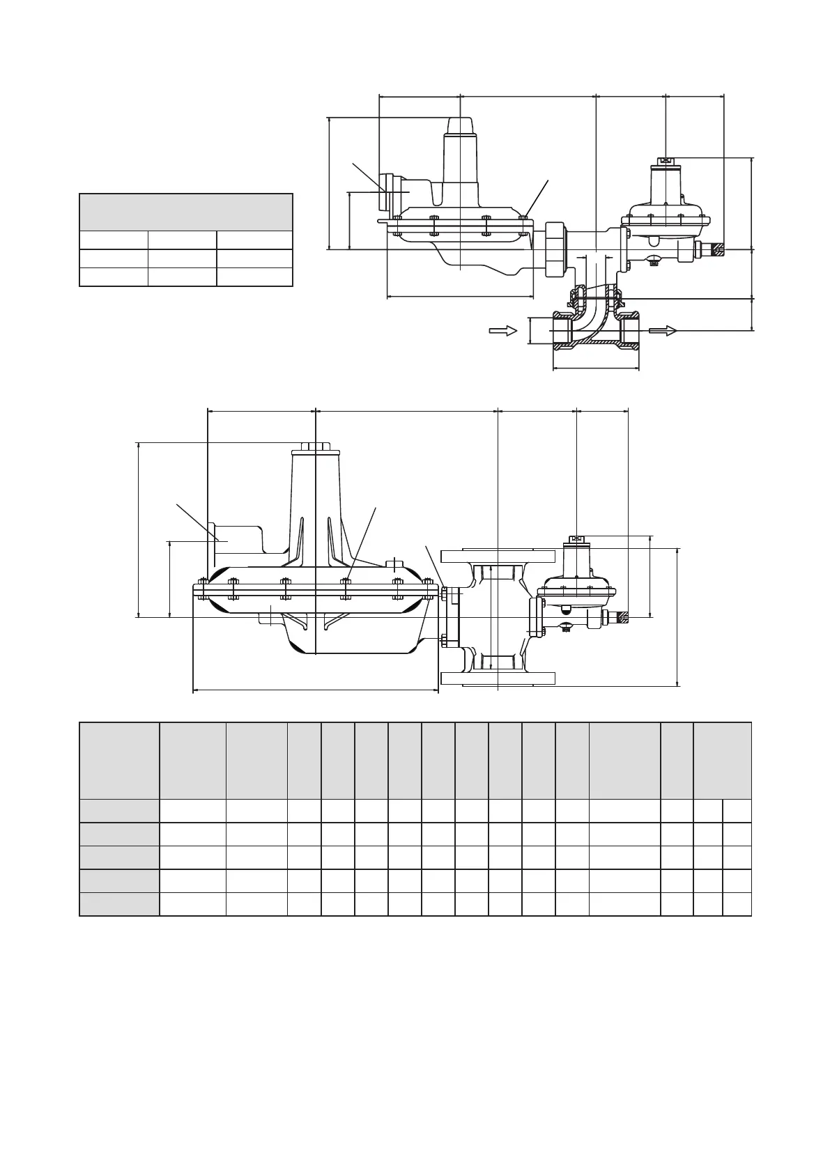
42
E
J
D
F
G
C1
H
C
A
K
X
Y
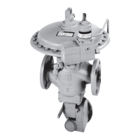
E
J
17 0
90
G
H
63
N
L
R
A
DN25
K
B
X
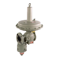
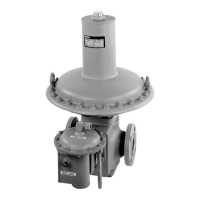
Einbaumaße / Dimensions
Max. Anzugsmomente / Torque of fastening
x) Schrauben am Membrangehäuse / Screws of diaphragm housing : max 10 Nm
y) Schrauben am Verbindungsflansch, Membrangehäuse zu Ventilkörper /
Screws of the connection flange, diaphragm housing to body : max 13 Nm.
(1) Gehäuse mit Gewindeanschluss / Body with thread connection
(2) Gehäuse mit Flanschanschluss / Body with flange connection
Type 133-E
Type 133/233/244
42
Tabelle für Anschlusstück /
Table of Connection piece
R
L N
Rp 1
110 41
Rp 1 1/2 140 50
Ausführung/
Version
Type
Gewinde-
Größe/
Thread-
Dimension
Flansch/
Flange
ØA B C1
(1)
C
(2)
D E F G H J
Atmungs-
Anschluss/
Breathering-
Connection
K ca. kg
(1) (2)
133-
3/4“ / 1”
DN 25 190 170 100 160 170 100 100 60 120 Rp 3/4“ 74 4 6
233-12
1 1/2”
DN 40 350 250 150 200 260 155 110 60 120 Rp 1” 110 11 15
233/244-12
- DN 50 350 250
- 200 260 155 110 60 120 Rp 1” 110 - 16
233-8
1 1/2” DN 40 260 250 150 200 220 125
110 60 120 Rp 1” 105 9 13
233/244-8
- DN 50 260 250 - 200 220 125 110 60 120 Rp 1”
105 - 14