Copyright 2010, Itron, Alle Rechte vorbehalten, Dokument: Instruction_manual_G10 to G100__2012.08.08.docx
CE Declaration of Conformity
Itron GmbH
Hardeckstraße 2
D-76185 Karlsruhe
Declares that the product type
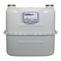
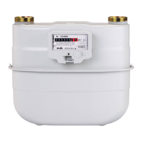
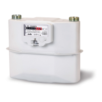
Diaphragm Gas Meters G10 to G100
is designed and manufactured in conformity with the following directives:
1. 97/23/EG; Pressure Equipment Directive (PED); Module A (Category II);
Concerns only pressure class > 0,5bar to max. 1 bar (screwed meter casing).
Applicable standard: EN 1359:1998 + A1:2006
This module A1 is supervised by TÜV Süd-Deutschland Bau- und Betrieb GmbH (CE:
0036); Durmersheimerstr. 145, 76189 Karlsruhe.
EC Certificate N°: BB-NDD-KAR-01/08/4648676/001
2. 94/9/EG (ATEX); Annex II
N°: ZELM 11 ATEX 3464
II 2 G c IIC T5
Applicable standards: EN 13463-1:2009 and EN 13463-5 :2003
The technical documents according 94/9/EG, Annex VIII are registered at the notified
body ZELM Ex (CE: 0820).
(Acknowledgment N°: ZELM Ex 0731119887)
3. 2004/22/EC (MID)
Annex B with EC type examination certificates:
G10/G16 : EC Certificate N°: DE-07-MI002-PTB013, Rev. 02
G25 to G100 : EC Certificate N°: DE-10-MI002-PTB004, Rev. 01
Annex D is supervised by:
Physikalisch-Technische Bundesanstalt (CE: 0102)
Bundesallee 100, D-38116 Braunschweig
EC Certificate N°: DE-10-AQ-PTB009MID
4. Only if electrical devices are used:
89/336/EEC-89 (electromagnetic compatibility) regarding following Standards:
EN61000-6-2: 2006-03 and EN61000-6-3:2007-09.
Karlsruhe, 23.07.2012
P. Garcia
Head of Production
Instruction Manual
for Diaphragm Gas Meters G10 to G100
Keep this manual easily accessible for all users.
Please respect all national rules for installation,
operation and service of gas meters.
1. Important safety instructions:
• The diaphragm gas meter G10 to G100 is designed to measure gases of the 1st, 2nd and
3rd gas family as specified in EN437 as well as various filtered and non-corrosive gases.
If aggressive gases are to be measured, please contact Itron for specific advice or to
obtain a special version of the meter.
• If there is a risk of internal or external corrosion, inspect the device regularly. If the
device is clearly affected by corrosion, put it out of use.
• Before installation, the meter must be checked for possible damages during transport.
Any damage must be reported immediately to the carrier. Never install a damaged
meter.
• The operating conditions indicated on the nameplate, especially maximum admissible
operation pressure and flow rate have to be respected; eventually provide appropriate
security equipment.
• The device is not designed to withstand earthquakes and floods.
• Repairs of the device must be performed by skilled staff or properly instructed personnel
only. Repairs must be followed by a leakage test with 1.1 x PS. The guarantee only covers
repairs done by Itron.
• The maximum tightening torque of the pressure tapping point is 4 Nm, must not exceed
1 Nm for the thermowell (both connections available on request)
• After connecting a pressure sensor, check the tightness of the connection.
• Relieve internal pressure completely before removing the device. Ensure proper
ventilation because of possible escapes of residual gas. Cap the inlet/outlet connections.
• Only screwed casing version: The inner volume (V) of the meter in litre is:
ACE10/16: V = 21,7L (not PED-relevant); G25; V = 36 L (PED); G40; V = 90 L
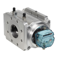
2. Electrical accessories:
Remarks about using the meter in potentially hazardous areas (ATEX):
• Tools with Ex-approval must be used for assembly, removal or repair in a hazardous area.
• The meter must not be exposed to flames, ionising radiation or ultrasound.
• The meter must be taken in account in the lightning evaluation of the complete
installation.