14
Section 3 Model 763A Gage Pressure Transmitter
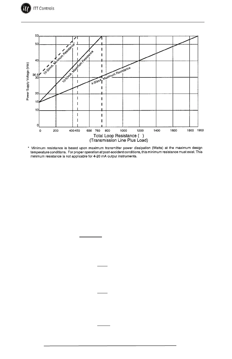
Figure 3.3—Power supply and loop resistance
Load and Line Resistance Calculations
Use the following method to calculate values of load and line resistance:
Example 1: (Maximum loop resistance for 10-50 mA system):
V
DC
= 53 Vdc T
VDC
= 15 Vdc
I
DC
= 50 mA
R
T
= = 760 Ohms
0.05
53-15
Example 2: (Maximum loop resistance for 4-20 mA system):
V
DC
= 53 Vdc T
VDC
= 15 Vdc
I
DC
= 20 mA
R
T
= = 1,900 Ohms
0.02
53-15
Example 3: (Calculation to determine maximum loop resistance with
power supply ≥30.5 Vdc, but ≤ 53 Vdc for 10-50 mA systems):
V
DC
= 40 Vdc T
VDC
= 30.5 Vdc
I
DC
= 50 mA
R
T
= = 190 Ohms
0.05
40-30.5
Transmitter Current = I
DC
(20 mA or 50 mA)
R
T
= V
DC
- T
VDC
I
DC
Total Loop Resistance (R
T
) = R
Line
+ R
Load
+ R
Ext
Power Supply Voltage = V
DC
(53 V max. for 4-20 mA or 10-50 mA Systems)
Maximum Transmitter Voltage = T
VDC
(15 V for both 4-20 mA and 10-50 mA Systems)
Minimum Transmitter Voltage = T
VDC
(30.5 V for 10-50 mA Systems)
www.ittcontrols.com contact@ittcontrols.com