24
Section 4 Model 763A Gage Pressure Transmitter
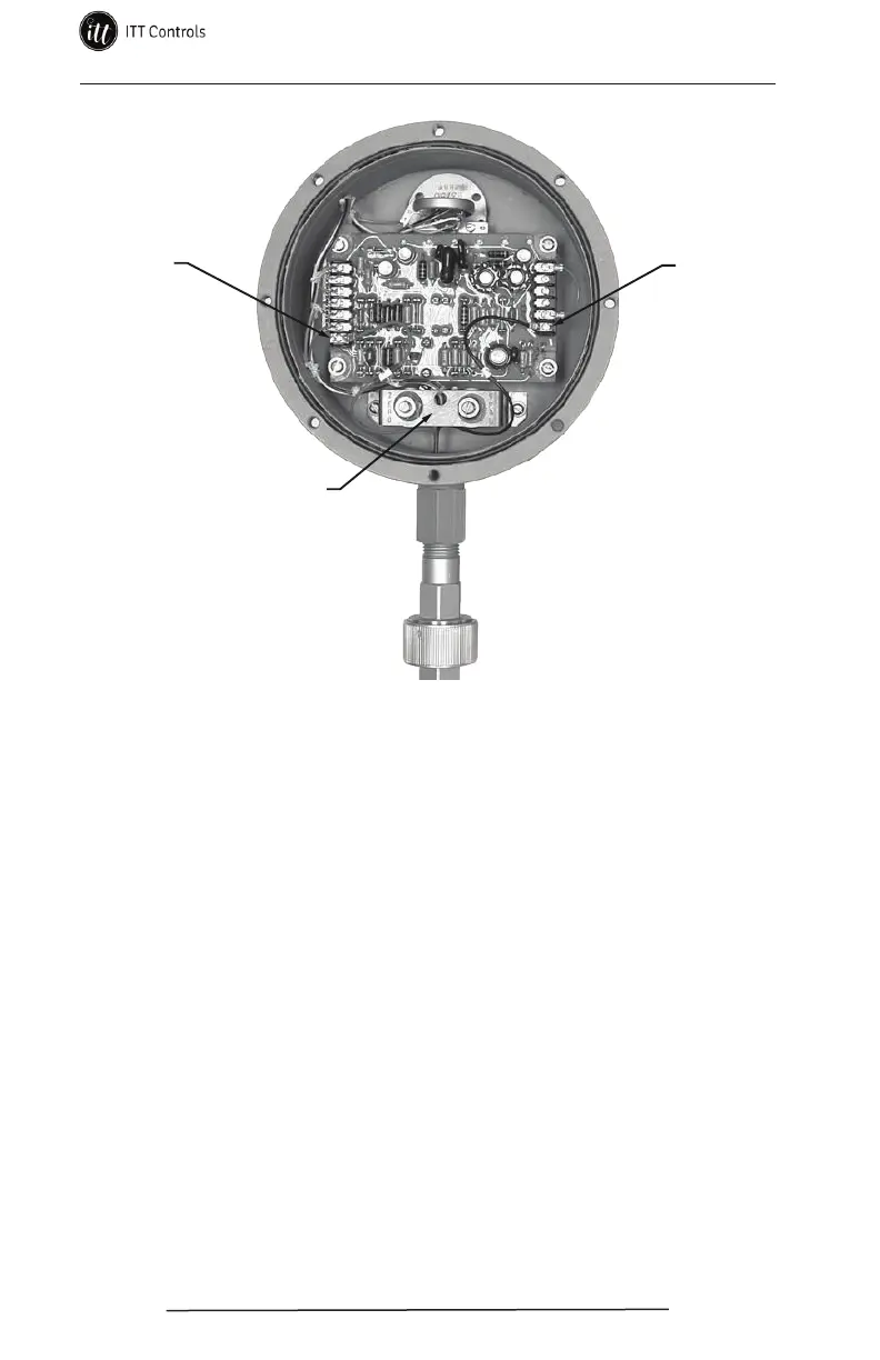
Zero and span bracket
TB1-7
(red)
TB2-6
(black)
Figure 4.2—Wiring for EGS quick disconnect connector assembly
Removal of the Barton Style Connector Assembly
A special connector tool is required for removal of the Barton style connector
assembly, and is available from Cameron (Part No. 9A-0764-1174B).
To remove the Barton style connector assembly, perform the following steps.
1. Remove the transmitter from service and de-energize it.
2. Remove the transmitter cover (see procedure on page 21).
3. Disconnect the red and black signal leads from the transmitter circuit
board (TB 1-7 and TB 2-6) as shown in Figure 4.3, .
4. Insert the connector tool (Part No. 9A-0764-1174B) into the transmitter
conduit hub opening and carefully unscrew and remove the connector as-
sembly (connector and two O-rings) as shown in Figure 4.3, page 25.
Installation of the Barton Style Connector Assembly
To install a Barton style connector assembly, perform the following steps:
1. Mate the connector tool (Part No. 9A-0764-1174B) to the connector as-
sembly.
2. Install two O-rings onto the threaded end of the connector assembly.
Lightly lubricate the threads and O-rings with DC High Vacuum Grease.
www.ittcontrols.com contact@ittcontrols.com