25
Model 763A Gage Pressure Transmitter Section 4
3. Screw the assembly into the transmitter conduit hub opening.
4. Replace the two mounting screws in the Zero and Span mounting bracket
and tighten.
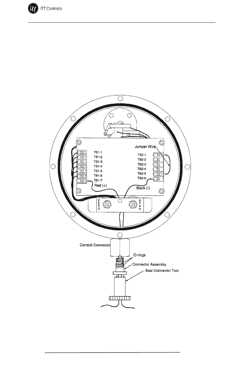
5. Connect the red and black signal leads of the connector assembly to the
transmitter circuit board (TB 1-7 and TB 2-6).
6. Install new O-rings into the grooves of the transmitter cover. Lightly
lubricate the O-rings with DC High Vacuum Grease.
7. Replace the transmitter cover (see procedure on page 21).
Figure 4.3—Wiring for connector assembly (leadwire) replacement,
shown with Barton style connector assembly
www.ittcontrols.com contact@ittcontrols.com