17
Model 763A Gage Pressure Transmitter Section 3
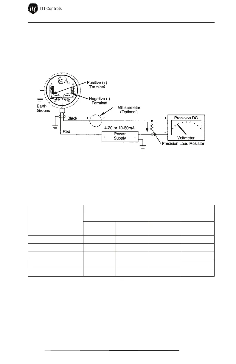
2. Connect the electrical readout device to the transmitter as shown in Fig-
ure 3.5 for either current or voltage readout. If the transmitter is equipped
to an EGS Quick Disconnect connector assembly, secure the two mating
connectors with the bayonet ring (see page 22 for details).
3. With minimum calibration pressure applied, check the output signal.
Figure 3.5—Electrical connections for calibration
Table 3.1 presents the transmitter output values in current or voltage,
along with the associated tolerance, for both the 4-20 mA and 10-50 mA
variations. If the output signal is not the required reading, adjust the zero
control potentiometer in the compensating direction.
Table 3.1—Calibration Checkpoints
Applied Calibration
Pressure Checkpoint
(% of Full Scale)
Output*
4-20 mA Transmitter** 10-50 mA Transmitter***
Current
(±0.08 mA)
Voltage
(±0.04 Vdc)
Current
(±0.2 mA)
Voltage
(±0.04 Vdc)
0% 4 mA 2 Vdc 10 mA 2 Vdc
25% 8 mA 4 Vdc 20 mA 4 Vdc
50% 12 mA 6 Vdc 30 mA 6 Vdc
75% 16 mA 8 Vdc 40 mA 8 Vdc
100% 20 mA 10 Vdc 50 mA 10 Vdc
*This value includes the effects of conformance (non-linearity), deadband, hysteresis, and repeatability.
**This value was obtained using a 500-Ohm load resistor.
***This value was obtained using a 200-Ohm load resistor.
4. Apply calibration pressure corresponding to maximum output. If the
output signal is not the required reading per Table 3.1, adjust the span
control potentiometer in the compensating direction.
5. Zero and span controls have a minimum of interaction when adjusted;
however, steps 3 and 4 may be repeated as necessary to obtain desired
accuracy.
www.ittcontrols.com contact@ittcontrols.com