Operating Instruction
12
www.hydrovar.com
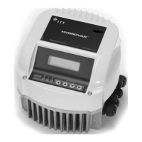
4 Electrical connection, control terminals and Display unit
Do the hydraulic assembling first before starting the electrical connection.
a) Open the 4 screws of the cover and remove the top cover.
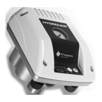
b) Connect the motor cable and the supply cable.
c) If required, connect the control cable for the external release contact and the
thermistor (PTC). If they are not used; these inputs have to be bridged.
Cable gland type Suitable cable
diameter
Pieces
M20x1,5 7-13 [mm] 1
M16x1,5 4,5-10 [mm] 2
M12x1,5 3,5-7 [mm] 1
Do not connect the electronic ground with the other voltage potentials!
There is only single isolation of the control voltage. Between ground and
GND of the control voltage there can occur voltage levels >100VAC!
Connected relays or switches therefore have to have double isolated
contacts.
Terminals:
X4/ 1 GND
2 External release (On / Off)
3 GND
4 Thermistor
 Loading...