A
amandachandlerJul 31, 2025
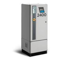
What to do if the ITW GSE Hobart 2400 Compact Portable Generator display is blank?
- BburkedebraJul 31, 2025
If the ITW GSE Portable Generator's display is blank, you should check Q6 (Circuit Breaker) and fuse F3 at the Interface Board A2, paying attention to the corresponding LED D8.