L
Lisa WalkerAug 14, 2025
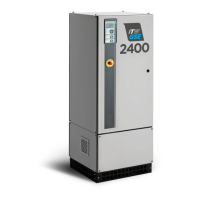
What to do if emergency stop is activated on ITW GSE Hobart 2400?
- RRyan KempAug 14, 2025
If the emergency stop is activated on your ITW GSE Portable Generator, release the emergency stop and then press start to reset the system.