EasyManuals Logo

IVT 12KHR-N Service Manual

IVT 12KHR-N
35 pages
To Next Page IconTo Next Page
To Previous Page IconTo Previous Page
Page #21 background imageLoading...
Page #21 background image
12KHR-N
2 – 17
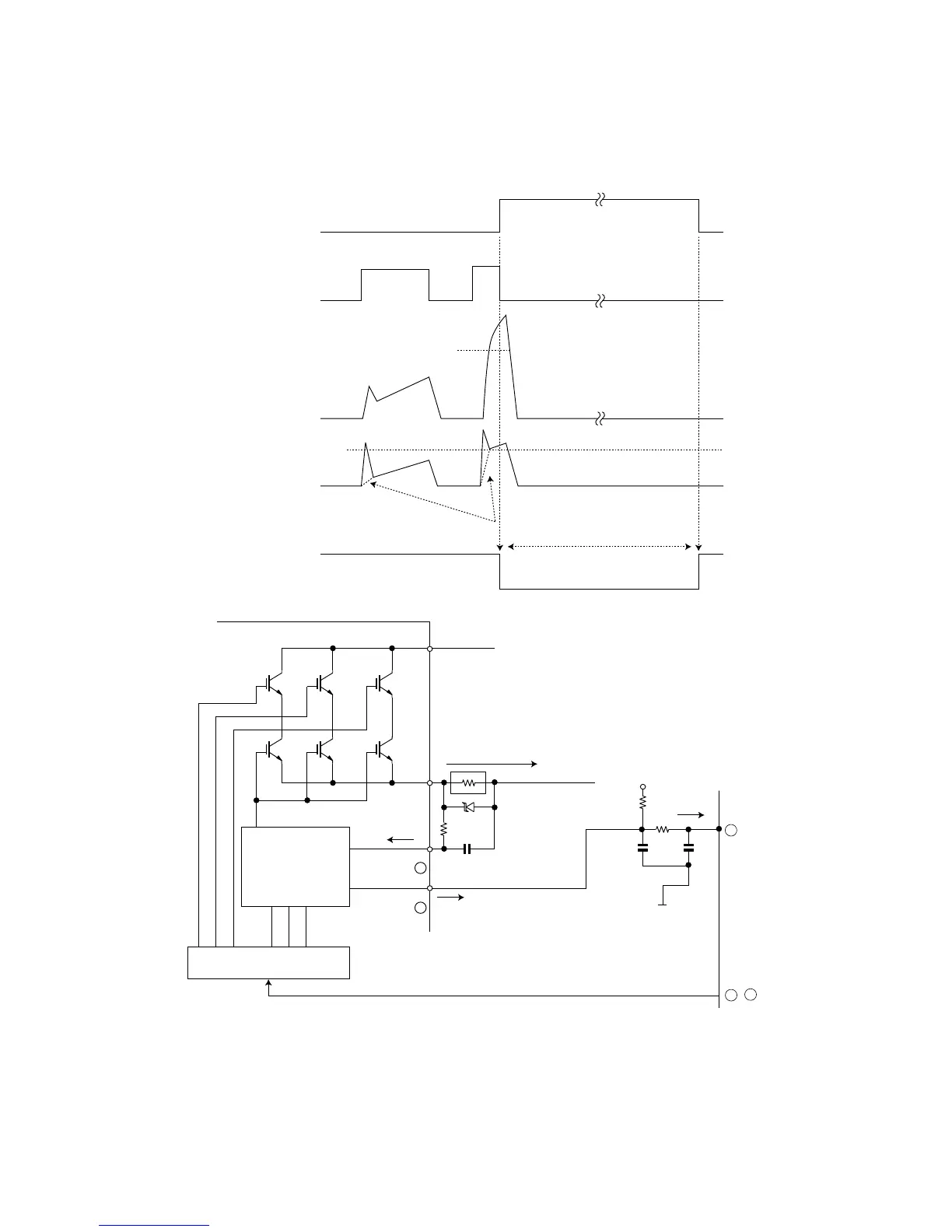
4.1.2 DC overcurrent detection circuit
When a current of about 25 A or higher flows through the shunt resistance (R49) on the control printed circuit board (PCB), the voltage at this resis-
tance is input to IPM CIN pin (15). Then, the gate voltage of the lower-phase IGBT (LU, LV, LW) inside the IPM turns OFF to cut off the overcurrent. At
the same time, an L output of more then 20Ps. is generated from IPM Fo pin (14), and this results in an L input to overcurrent detection input pin (34)
of the microcomputer (IC1) and turns OFF the PWM signal output (IC1 pins (51) through (56)) to the IGBT gate.
SET
RESET
(About 25 A)
SC
SC reference voltage
Delay by CR time constant circuit
More than 20ǴU
a1
Protection circuit status
Output current Ic (A)
Sense voltage relative
to shunt resistance
Error output Fo
(Lower phase)
Internal IGBT gate
IPM overcurrent
detection circuit
5V
0V
IC1
R49
Overcurrent
Shunt resistance
P
N
CiN
FO
14
15
34
51 ~ 56
IPM

Questions and Answers:

Question and Answer IconNeed help?

Do you have a question about the IVT 12KHR-N and is the answer not in the manual?

IVT 12KHR-N Specifications

General IconGeneral
BrandIVT
Model12KHR-N
CategoryHeat Pump
LanguageEnglish

Related product manuals