Do you have a question about the IVT Optima 1100 and is the answer not in the manual?
Pre-installation checks for the heat pump and heating system.
A step-by-step checklist for the installation process.
Lists rubber feet and circlip pliers included with the heat pump.
Lists user guides, installation guide, and sensors for the electric boiler.
Lists optional accessories like room sensor, softstarter, and heating cable.
Guidelines for safe transport and storage of the heat pump and electric boiler.
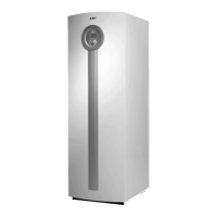
Recommendations for outdoor placement, base, sound, and clearances for optimal operation.
Defines the operational temperature limits for the heat pump.
Explains control methods using outdoor and room sensors.
Describes the hot gas defrosting principle and fan defrost function.
Identifies and illustrates locations of various temperature sensors (T1-T12).
Details the CANbus communication system, cabling, and termination requirements.
Explains the function of switch S1 for CANbus loop termination.
Detailed diagram showing connection points on the electric boiler.
Detailed diagram showing connection points on the heat pump.
Illustration of the optional power guard circuit board's layout.
Specifies clearance and space requirements for the Optima heat pump installation.
Specifies clearance and space requirements for the 290 A/W electric boiler installation.
Details pipe connection types, sizes, and routing for system integration.
Instructions for installing the particle filter on the incoming pipes for dirt removal.
Emphasizes the importance of flushing the heating system before connecting the heat pump.
Guidance on connecting the system components and relevant pipework.
Explains the operational principle of heat pump and electric boiler integration.
Step-by-step instructions for filling the heating system with water.
Step-by-step instructions for safely draining the heating system water.
Details connection instructions for room sensor, softstarter, and heating cable.
Information about the optional Power guard and its electrical connection.
Requirements and recommendations for safety switches and earth-fault breakers.
Explains the heat pump's emergency operation mode and its settings.
Schematic diagram showing electrical connections for the Optima heat pump.
Schematic diagram showing electrical connections for the 290 A/W electric boiler.
Illustrates terminal connections for Optima and 290 A/W, including Power guard.
Details for connecting power supply, CANbus, and heating cable to Optima.
Details for connecting power supply, CANbus, outdoor and room sensors.
Guide to accessing and using the installer and service menus for settings and maintenance.
Lists functions available in the customer and advanced menus.
Settings for heating system temperature, heat curve, and room sensor.
Settings for hot water generation, peak times, and temperature control.
Overview of temperature-related settings, sensors, and defrost parameters.
Parameters for managing the defrost cycle, including interval and time.
Functions for setting the date and time on the control unit.
Access to view and manage alarm logs, history, and warning logs.
Options for managing user access levels within the control unit.
Function to reset all settings to factory defaults.
Option to disable the audible alarm buzzer.
Displays the current software version of the control unit.
Pre-commissioning checks: filling, venting, and leak verification.
Initial steps to start the heat pump and select language and clock settings.
Procedure for carrying out basic settings in the Start up menu.
Instructions for setting the date and time during commissioning.
Setting for acknowledging the room sensor (T5) and its influence.
Setting the total output for electric additional heat based on the connected boiler.
How to manually check functions and components using the control panel.
Settings related to blocking compressor/fan or blocking additional heat function.
Procedure for changing the unit's display language.
Procedure for correcting sensor readings with specified limits.
Adjusting settings for fan defrost function based on humidity and frequency.
Using forced defrost to bypass timer and temperature conditions for defrost.
Deactivating crankcase heater based on outdoor temperature to save energy.
Setting the time for the anti-jamming run of pumps and fan to prevent seizing.
Configuring the duration of the audible alarm buzzer sound.
Setting the maximum value for T1, may need reduction for underfloor heating.
Adjusting contrast and brightness of the control unit's display.
Troubleshooting alarms related to low condenser temperature during initial start-up.
Steps to configure the power guard settings for load management.
Making necessary adaptations for heating/hot water settings, especially for underfloor heating.
Verification steps: flow, temperature difference, and radiator warmth for optimal performance.
Displays the remaining time before defrosting is permitted.
Calculates temperature difference for defrost control and compares to set points.
Max operating time for heat pump in heating mode with simultaneous hot water demand.
Max operating time for hot water with simultaneous heating demand.
Access to view the chronological log of all system alarms.
Provides detailed information about past alarms and their conditions.
Chronological storage of warning messages for system monitoring.
Table of default values for customer-adjustable menu settings.
Table of default values for installer-adjustable advanced menu settings.
Factory setting for room sensor temperature control.
Settings for adjusting temperature curves based on room sensor input.
Fine-tuning settings for temperature adjustments using the room sensor.
Factory setting for the duration of extra hot water supply.
Settings for heating system temperature, heat curve, and room sensor.
Settings for hot water generation, peak times, and temperature control.
Overview of temperature-related settings, sensors, and defrost parameters.
Parameters for managing the defrost cycle, including interval and time.
Factory settings for fan defrost interval and time.
Settings for start delay, additional heat, and mixing valve operation.
Settings for power guard, supply voltage, and main fuse configuration.
Factory settings for mixing valve neutral zone and time extensions.
Functions for setting the date and time on the control unit.
Options for managing alarm and warning logs.
Settings for managing user access levels within the control unit.
Function to reset all settings to factory defaults.
Option to disable the audible alarm buzzer.
Technical data for Optima heat pump models 600, 900, and 1100.
Technical data for the IVT 290 A/W electric boiler.
Specifies sound pressure levels for Optima heat pumps at different distances.
Table showing sensor resistance values at various temperatures for calibration.