21
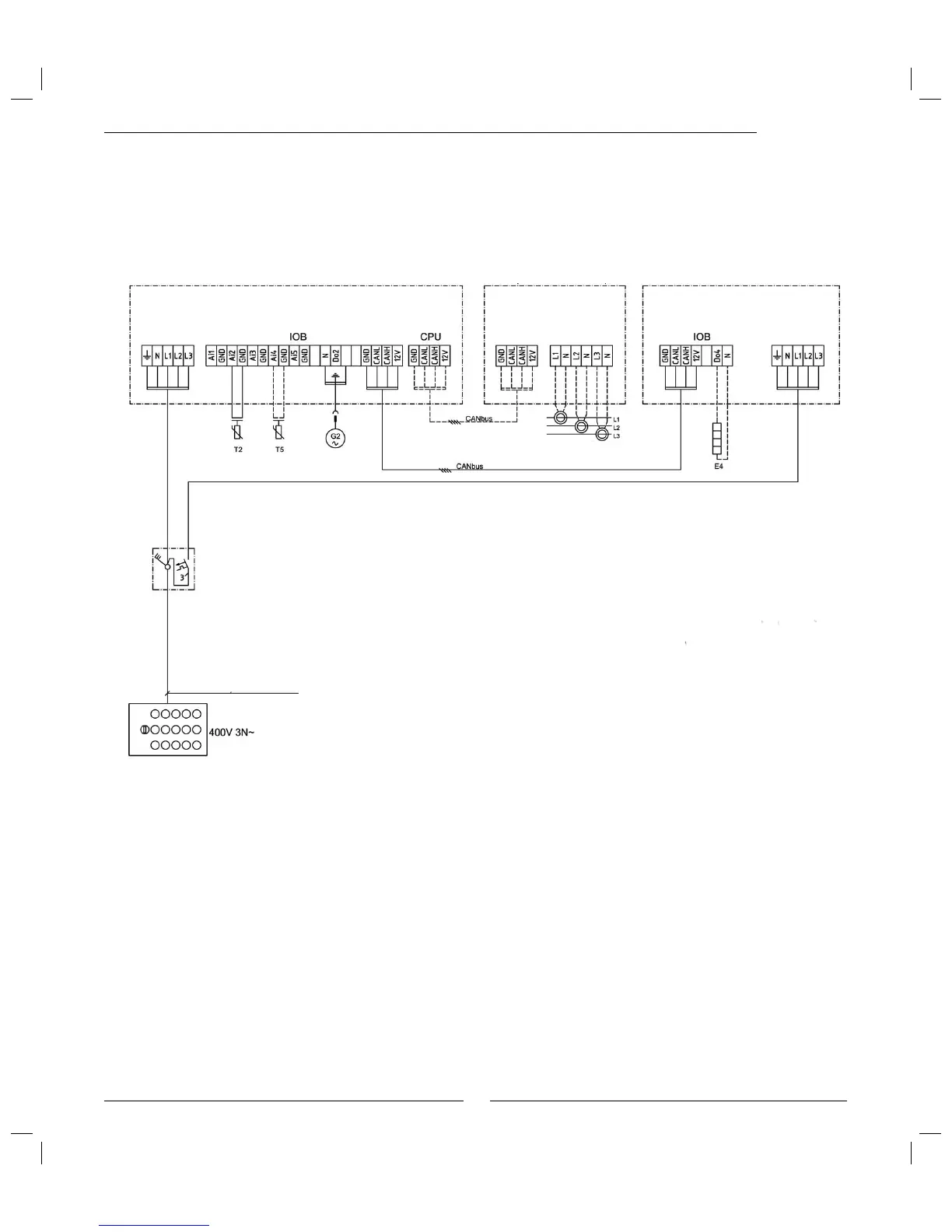
Terminal diagram Optima -290 A/W
E4: Heating cable in draining pipe, accessory
G2: To protect the heat carrier pump G2 during stand alone
operation of 290 A/W it is not connected from the factory.
If Optima is to be used G2 is connected with the quick
connector in the distribution box.
T2: Outdoor sensor
T5: Room sensor, accessory
Standard enclosure with
safety switch and fusing for
Optima 10A
Fusing:
16A for 9 kW electric additional heat
25A for 13.5 kW electric additional heat
290 A/W
Power guard (accessory) Optima
Measurement transformers
on the incoming supply to
the house fuse box.
Power guard, option.
When the power guard is installed
last in the CANbus loop S1 must be
terminated.
Wiring diagram
 Loading...


