13
Pipe connections
The following connections are made to the electric boiler:
A 32 mm plastic pipe is drawn from the waste water pipe to the fl oor drain.
The fl ow is connected to the inlet marked Forward fl ow.
The return is connected to the inlet marked Return fl ow. Cold water and
hot water are connected to inlets marked Cold water and Hot water.
The following connections are made to the heat pump:
A 32 mm plastic pipe is drawn from the drainage pipe to the fl oor drain.
Pipe dimensions
Riser/return
Clamping ring connection mm ø22
CW and HW
Clamping ring connection mm ø22
To/from connections
Clamping ring connection mm ø22 (in the electric boiler)
Clamping ring connection mm ø28 (n the heat pump)
Waste water/drainage mm ø32 (in both)
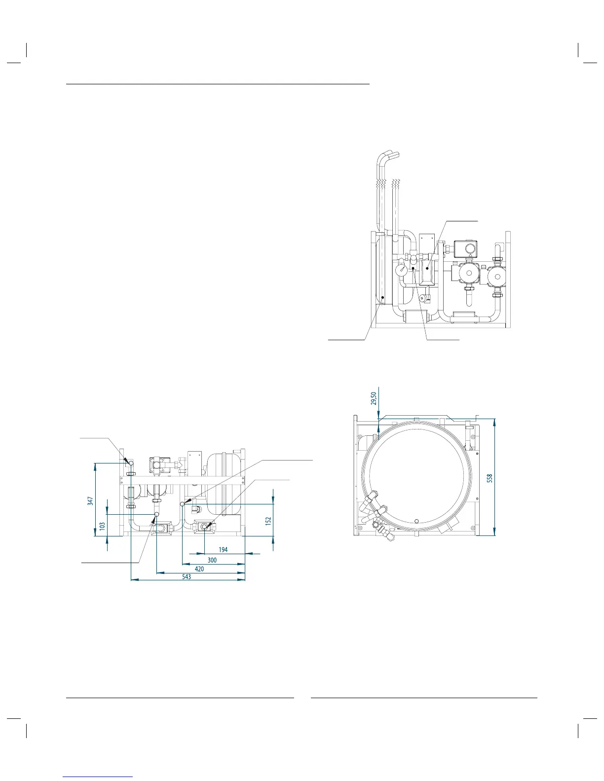
290 A/W front view
Waste water
Hot water
Cold water
View connection area 290 A/W seen from behind
290 A/W top view
Riser heating system
Return heating system
Fit the particle Þ lter
The task of the particle fi lter is to fi lter out dirt before it can enter the heat
pump. Accordingly, the supplied particle fi lters should always be fi tted on
the incoming pipes on the hot side. (See page. 15: V21)
It should be fi tted as close to the heat pump as possible and be horizontal.
1) From the heat pump.
(Connect to 1) in the heat pump picture.
2) To the heat pump.
(Connect to 2) in the heat pump picture.
Dimensions, clearance and plumbing connections
 Loading...


