19
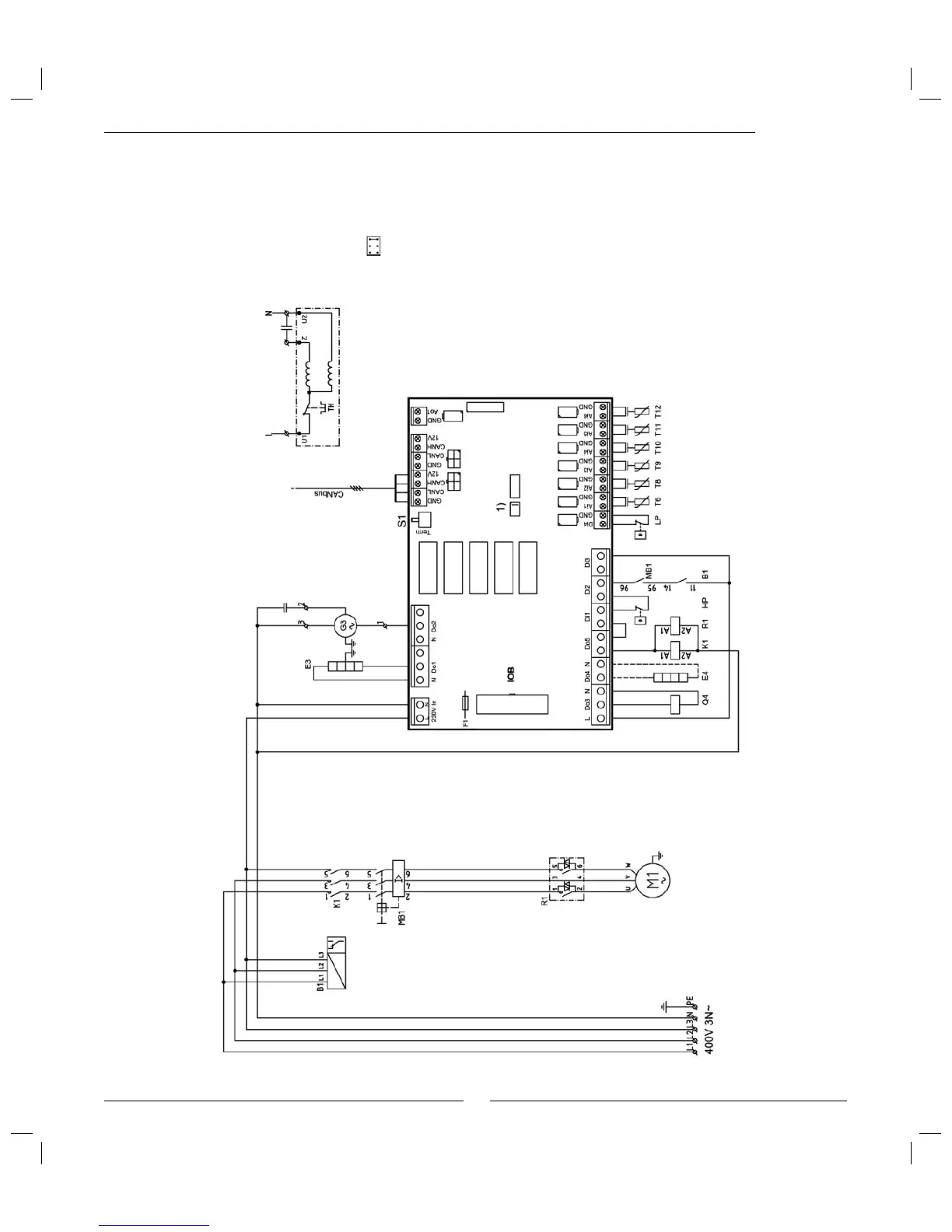
Wiring diagram Optima
Wiring diagram
B1: Phase sequence monitor
E3: Crankcase heating
E4: Any heating cable
F1: Miniature circuit breakers
G3: Fan
K1: Contactor compressor
M1: Compressor
MB2: Motor cut-out compressor
Q4: Four-way valve
R1: Soft starter
HP: High pressure switch
LP: Low pressure switch
T6: Compressor hot gas
T8: Heat transfer ß uid out
T9: Heat transfer ß uid in
T10: Condenser
T11: Evaporator temp
T12: Air intake
To the electric
boiler
Fan G3
Blue
Brown
Black
S1 must be in "Term" position on
the Þ rst and last circuit board in
the CANbus loop.
1) Strap
 Loading...


