20
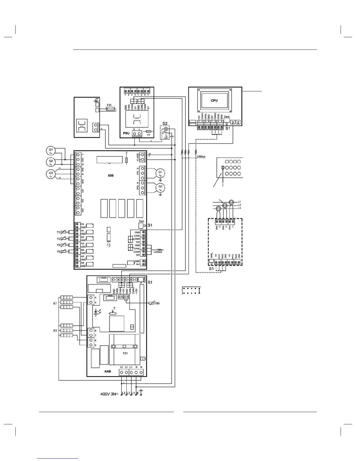
Wiring diagram 290 A/W
E1: Electric element 4.5/6.75 kW
E2: Electric element 4.5/6.75 kW
F1: Miniature circuit breakers
F21: Overheating protection
F31: Electronic anode in hot water heater
G1: Pump for heating system
G2: Heat carrier pump
Q1: Three-way valve
Q2: Three-way valve
Q3: Mixing valve
S1: Termination switch
S2: Switch emergency operation
T: Emergency thermostat
T1: Sensor ß ow heating system
T2: Outdoor sensor
T3: Hot water sensor
T5: Any room sensor, accessory
T99: Emergency operation sensor
To the heat
pump
1) Strap
Display card
Wiring diagram
Open
Open
Close
Power guard
(accessory)
The current transformers
are installed on the house’s
incoming power supply.
S1 must be in "Term" position on
the Þ rst and last circuit board in
the CANbus loop.
 Loading...


