23
External connections 290 A/W
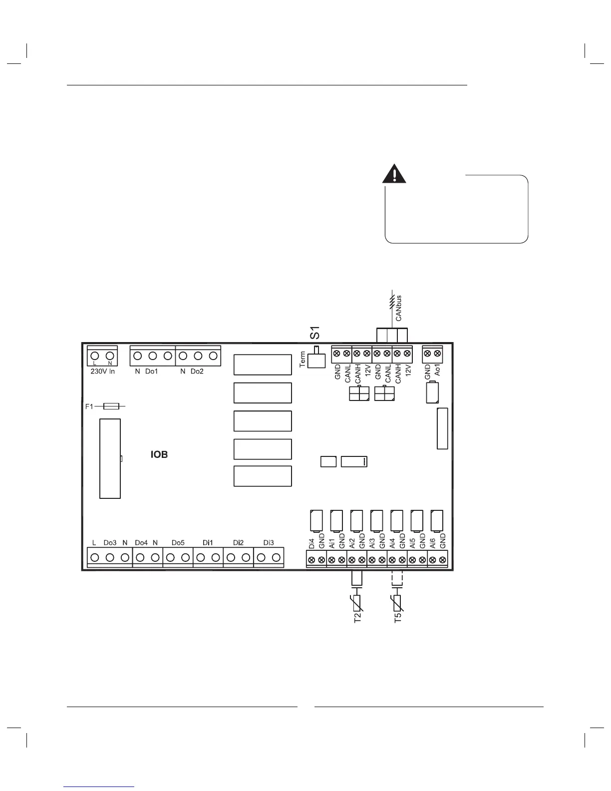
Power supply:
Connect to terminals L1, L2, L3, N and PE.
CANbus:
Communication cable between the heat pump and electric boiler.
Connect to terminals GND, CANL, CANH and 12V. See more under
section CANbus.
T2, Outdoor sensor:
Connect to terminals Ai2 and GND.
T5, Room sensor:
Accessory. Connect if room sensor infl uence is required. Connect to
terminals Ai4 and GND.
External connections
Warning
Do not mix up the 12V and CAN-
bus connections! If 12V (or other
incorrect voltage) is supplied to the
CANbus contacts the processors in the
CANbus are destroyed.
 Loading...


