12KHR-N
1 – 3
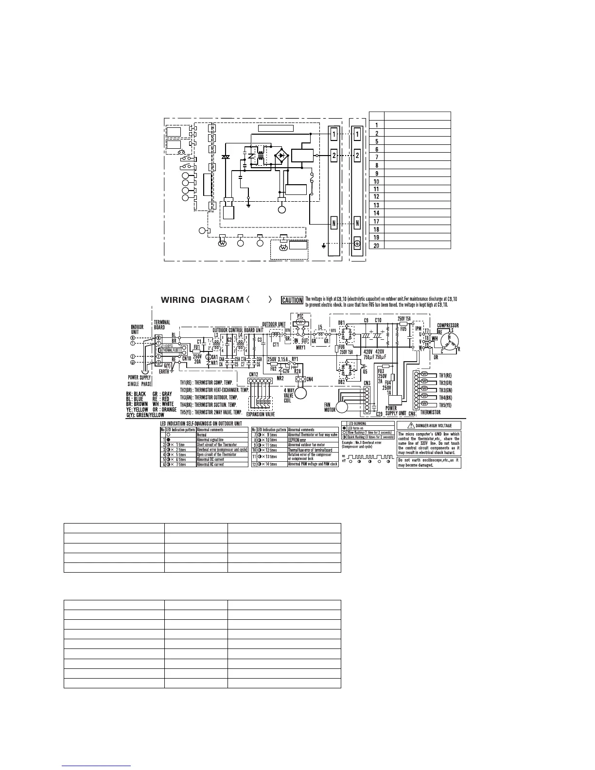
[3] WIRING DIAGRAM
1. Indoor unit
2. Outdoor unit
[4] ELECTRICAL PARTS
1. Indoor unit
2. Outdoor Unit
DESCRIPTION MODEL REMARKS
Indoor fan motor MLB395 DC motor
Indoor fan motor capacitor – –
Transformer – –
FUSE1 – QFS-GA078JBZZ (250V, 3.15A)
DESCRIPTION MODEL REMARKS
Compressor DA111A1F22F DC motor
Outdoor fan motor MLB078 DC motor
Outdoor fan motor capacitor – –
Fu4 – QFS-GA064JBZZ(250V, 1A)
Fu3 – QFS-GA051JBZZ(250V, 2A)
Fu2 – QFS-GA052JBZZ(250V, 3.15A)
Fu1 – QFS-CA001JBZZ(250V, 20A)
Fu5, 6 – QFS-CA002JBZZ(250V, 15A)
ޛ
%%
ޜ
%0
%0
$%0
$%0
.178'4
*14+<106#.
5'0514$1#4&
70+6
%0
411/6'/2
6*'4/+5614
2+2'6'/2
6*'4/+5614
%
5
%.756'4
)'0'4#614
%#76+10*+)*81.6#)'
.'(6
*11-
4+)*6
*11-
%0
%0
%0
$%0$%0
8#
4'%'+8'4
$1#4&70+6
$%0
%0
%0
.'(6
2#0'.
4+)*6
2#0'.
%0
%0
%0
$%0
%0
$%0
2#0'.
59+6%*
%0
%0
6*14
.178'4
8'46+%#.4+)*6
%0
%0
+06'4%100'%6+10
˴$1#4&70+6
2#0'.
59+6%*
˴$4
㧔$-㧕
(75'
(7
%0
%0
%0
$%0
6*
&+52.#;
$1#4&70+6
#7:
59
(#0/1614
0(
&$
5'4+#.
5+)0#.
%+4%7+6
9*
4&
6'4/+0#.
$1#4&
+0&11470+6176&11470+6
%10641.$1#4&70+6
W I R I N G D I A G R A M
INVERTER AIR-CONDITIONER
219'45722.;
70+6
%0
554
04
%
%
%
'
/
//
.178'4
8'46+%#..'(6
/
/
/
/
/
UNIT TO UNIT CORD
);
$-$.#%-
$4$4190
9*9*+6'
4&4'&
);)4''0;'..19
1414#0)'
6'4/+0#.
$1#4&
LED INDICATION FOR SELF-DIAGNOSIS
Blinking NO.
#DPQTOCN%QPVGPVU
Short circuit of the outdoor thermistor
Overheat of the compressor
EEPROM error of indoor unit
Abnormal
fa
n
m
otor of
in
door uni
t
Sho
rt circuit of serial si
g
nal line
Open circuit of serial signal line
Abnormal PAM voltage and clock signal
Abnormal compressor rotation
Abnormal outdoor fan motor
Abnormal thermistor of four way valve
Abnormal AC current
DC over current
Open circuit of the outdoor thermistor
<Indication of the abnormal condition>
LED indicator will blink, if the set is in abnormal condition.
Thermal fuse error of outdoor unit
Abnormal wire connection
EEPROM error of outdoor unit
);
FL A S H
CO N N ECTO R
%0
$%0
 Loading...