AYXP12FRN
3 – 7
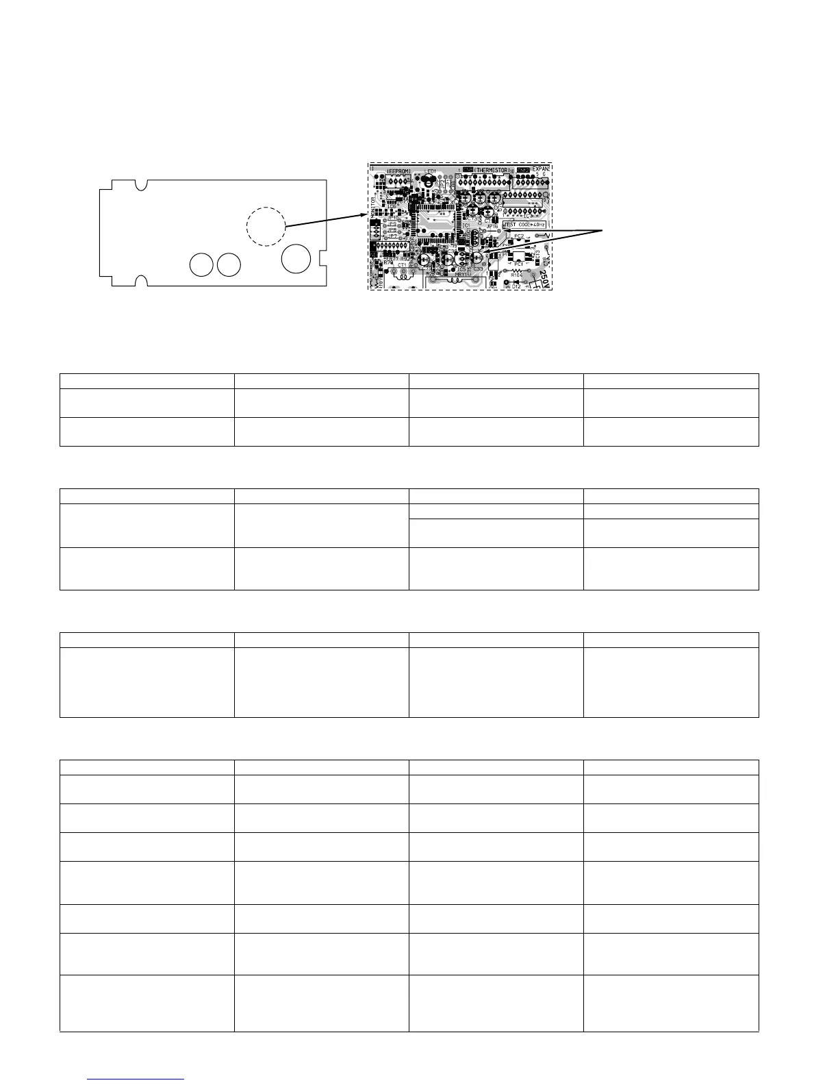
[4] HOW TO OPERATE THE OUTDOOR UNIT INDEPENDENTLY
1. Cooling in 40 Hz fixed mode
To operate the outdoor unit independently, short-circuit the sections indicated by arrows in the diagram below with an adapter, and apply 230 VAC
between (1) and (N) on the terminal board of the outdoor unit. This allows the outdoor unit to be operated in cooling mode independently.
(Do not operate the outdoor unit in this condition for an extended period of time.)
[5] GENERAL TROUBLESHOOTING CHART
1. Indoor unit does not turn on
2. Indoor unit fan does not operate
3. Indoor unit fan speed does not change
4. Remote control signal is not received
Main cause Inspection method Normal value/condition Remedy
Cracked PWB.
(Cracked pattern)
Check visually. There should be no cracking in
PWB or pattern.
Replace PWB.
Open-circuit in FU1 (250 V, 3 A),
FU2 (250 V, 3 A)
Check melting of FU1, FU2. There should be no open-circuit. Replace PWB.
Main cause Inspection method Normal value/condition Remedy
Open-circuit in heat exchanger
thermistor (TH2) (in heating oper-
ation)
Measure thermistor resistance
(dismount for check).
– 1 Replace thermistor.
There should be no open-circuit
or faulty contact.
Replace thermistor.
Disconnected heat exchanger
thermistor (TH2) (in heating oper-
ation)
Inspect connector on PWB.
Check thermistor installation con-
dition.
Thermistor should not be discon-
nected.
Install correctly.
Main cause Inspection method Normal value/condition Remedy
Remote control not designed to
allow fan speed change.
Check operation mode. Fan speed should change except
during dehumidifying operation,
ventilation, light dehumidifying
operation, internally normal oper-
ation
Explain to user.
Main cause Inspection method Normal value/condition Remedy
Batteries at end of service life. Measure battery voltage. 2.5 V or higher (two batteries in
series connection)
Install new batteries.
Batteries installed incorrectly. Check battery direction. As indicated on battery compart-
ment.
Install batteries in indicated direc-
tion.
Lighting fixture is too close, or flu-
orescent lamp is burning out.
Turn off light and check. Signal should be received when
light is turned off.
Change light position or install
new fluorescent lamp.
Use Sevick light (Hitachi). Check if Sevick light (Hitachi) is
used.
Signal may not be received
sometimes due to effect of Sevick
light.
Replace light or change position.
Operating position/angle is inap-
propriate.
Operate within range specified in
manual.
Signal should be received within
range specified in manual.
Explain appropriate handling to
user.
Open-circuit or short-circuit in wir-
ing of light receiving section.
Check if wires of light receiving
section are caught.
Wires of light receiving section
should not have any damage
caused by pinching.
Replace wires of light receiving
section.
Defective light receiving unit. Check signal receiving circuit
(measure voltage between termi-
nals 2 and 3 of connector
BCN3B).
Tester indicator should move
when signal is received.
Replace PWB.
(L2)
C9C10
Connect with IC clip
Test mode cooling at 40 Hz
Connect with IC clip
Test mode cooling at 40 Hz
Short-circuit negative terminal of
capacitor (C33) and jumper wire
(JP16) using IC clip, etc.
 Loading...