EasyManua.ls Logo

IWAKI PUMPS EHN-B11VC - User Manual

Default Icon
68 pages
Print Icon
To Next Page IconTo Next Page
Loading...
©2010 IWAKI CO., LTD.
Thank you for choosing our product.
Please read through this instruction manual before use.
This instruction manual describes important precautions and instruc-
tions for the product. Always keep it on hand for quick reference.
Instruction manual
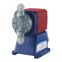
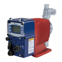
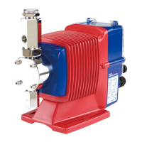
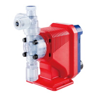
EHN-YN (multi-tube connection)
Iwaki
Electromagnetic Metering Pump
Safety instructions Overview Installation Operation Maintenance Specications
T944 '16/04
http://www.iwakipumps.jp
IWAKI CO.,LTD. 6-6 Kanda-Sudacho 2-chome Chiyoda-ku Tokyo 101-8558 Japan
TEL: +81 3 3254 2935 FAX: +81 3 3252 8892
European ofce
/ IWAKI Europe GmbH
TEL: +49 2154 9254 0 FAX: +49 2154 9254 48
Norway
/ IWAKI Norge AS
TEL: +47 23 38 49 00 FAX: +47 23 38 49 01
Australia
/ IWAKI Pumps Australia Pty Ltd.
TEL: +61 2 9899 2411 FAX: +61 2 9899 2421
Germany
/ IWAKI Europe GmbH
TEL: +49 2154 9254 50 FAX: +49 2154 9254 55
Sweden
/ IWAKI Sverige AB
TEL: +46 8 511 72900 FAX: +46 8 511 72922
China (Hong Kong)
/ IWAKI Pumps Co., Ltd.
TEL: +852 2607 1168 FAX: +852 2607 1000
Holland
/ IWAKI Europe GmbH (Netherlands Branch)
TEL: +31 74 2420011 FAX: +49 2154 9254 48
U.K.
/ IWAKI Pumps (U.K.) LTD.
TEL: +44 1743 231363 FAX: +44 1743 366507
China (Guangzhou) / GFTZ IWAKI Engineering & Trading Co., Ltd.
TEL: +86 20 84350603 FAX: +86 20 84359181
Italy
/ IWAKI Europe GmbH (Italy Branch)
TEL: +39 0444 371115 FAX: +39 0444 335350
U.S.A.
/ IWAKI America Inc.
TEL: +1 508 429 1440 FAX: +1 508 429 1386
China
/ IWAKI Pumps (Shanghai) Co., Ltd.
TEL: +86 21 6272 7502 FAX: +86 21 6272 6929
Spain
/ IWAKI Europe GmbH (Spain Branch)
TEL: +34 93 37 70 198 FAX: +34 93 47 40 991
Argentina
/ IWAKI America Inc. (Argentina Branch)
TEL: +54 11 4745 4116
Korea
/ IWAKI Korea Co., Ltd.
TEL: +82 2 2630 4800 FAX: +82 2 2630 4801
Belgium
/ IWAKI Belgium N.V.
TEL: +32 13 670200 FAX: FAX: +32 13 672030
Singapore
/ IWAKI Singapore Pte Ltd.
TEL: +65 6316 2028 FAX: +65 6316 3221
Taiwan
/ IWAKI Pumps Taiwan Co., Ltd.
TEL: +886 2 8227 6900 FAX: +886 2 8227 6818
Denmark
/ IWAKI Nordic A/S
TEL: +45 48 242345 FAX: +45 48 242346
Indonesia
/ IWAKI Singapore (Indonesia Branch)
TEL: +62 21 6906606 FAX: +62 21 6906612
Thailand
/ IWAKI (Thailand) Co., Ltd.
TEL: +66 2 322 2471 FAX: +66 2 322 2477
Finland
/ IWAKI Suomi Oy
TEL: +358 9 2745810 FAX: +358 9 2742715
Malaysia
/ IWAKIm SDN. BHD.
TEL: +60 3 7803 8807 FAX: +60 3 7803 4800
Vietnam
/ IWAKI Pumps Vietnam Co., Ltd.
TEL: +84 613 933456 FAX: +84 613 933399
France
/ IWAKI France S.A.
TEL: +33 1 69 63 33 70 FAX: +33 1 64 49 92 73

Table of Contents

Questions and Answers

Summary

Order Confirmation

Safety Instructions

Symbols and Warning Indicators

Explains warning symbols like WARNING, CAUTION, and their meanings.

Export Control Information

Notes that technical information may be subject to export controls and require licenses.

General Warnings

Lists critical safety warnings for operation, modification, and handling of the pump.

General Cautions

Details important cautions regarding qualified personnel, power usage, running dry, and environment.

Specific Safety Measures

Covers grounding, GFCI, preventative maintenance, pump damage, disposal, bolt checks, and relief valves.

Precautions for Use

Provides guidelines on installation locations, vibration, space, liquid handling, and pump care.

Overview

Introduction

Briefly introduces the pump characteristics, features, and part names covered in the section.

Pump Structure and Operation Principle

Describes the EHN series diaphragm pump structure and how electromagnetic force drives the reciprocating motion.

Pump Features

Highlights key features like multivoltage operation, high turndown ratio, IP rating, external control, and auto degassing.

Operational Functions

Introduces the different operational modes and functions available for the pump.

Manual Operation Mode

Explains how to run/stop the pump and adjust stroke rate using the keypad in manual mode.

EXT Mode

Details operation controlled by external signals, including proportional and digital control.

Proportional Control (Analog)

Describes adjusting stroke rate proportionally to a 0-20mA input signal.

Multiplier Setting (Digital)

Explains setting a multiplier to control shots per pulse based on external digital signals.

Divisor Setting (Digital)

Explains setting a divisor to control stroke rate based on external pulse signals.

STOP Function Control

Details how to control pump start/stop using external STOP signals (M-OF/M-ON).

Priming Function Operation

Describes using the priming function to run the pump at maximum stroke rate for degassing.

Part Names

Identifies and labels the main components of the pump.

Pump Components

Lists and illustrates the specific parts of the pump head and general assembly.

Operation Panel

Illustrates and describes the functions of the control panel keys and indicators.

Basic Display Indicators

Shows various display patterns and their corresponding operational states or settings.

Alarm Indicators

Displays indications shown when the pump operates beyond specified limits or encounters issues.

Other Display Indicators

Shows other display indicators like keypad lock status and priming mode.

Identification Codes

Explains the coding system used to identify pump series, drive units, and materials.

Pump Model Identification

Details the coding for Series Name, Drive Unit, and Diaphragm effective diameter.

Control Unit Identification

Explains the coding for Control Unit Model, Drive Unit, Control Unit Function, and Special Version.

Installation

Installation Points to Observe

Lists essential safety and procedural points to follow before and during pump installation.

Pump Mounting Procedure

Guides on selecting a suitable location and securely anchoring the pump using bolts.

Plumbing Connections

Covers connecting tubes to the pump and installing check valves.

Tube Connection Method

Provides step-by-step instructions for connecting tubing using fitting nuts and stoppers.

Air Vent Port Direction Adjustment

Explains how to adjust the direction of the air vent port for optimal operation.

Check Valve Installation

Details cases requiring check valve installation to prevent backflow, siphon, or overfeeding.

Tubing Layout Examples

Shows typical tubing configurations for flooded suction and suction lift applications.

Electrical Wiring

Covers wiring for power voltage, earthing, and external signals.

Wiring Points to Observe

Lists critical safety and procedural points for electrical wiring work.

Power Voltage and Earthing

Guides on connecting the power cable and ensuring proper earthing of the pump.

Surge Voltage Protection

Advises on measures to protect the control unit from surge voltage damage.

ON-OFF Control Relay Precautions

Provides precautions for controlling pump operation using mechanical relays.

Signal Wire Connections

Details applicable cables and connection methods for external signals.

Operation

Pre-Operation Checks

Lists checks to perform before starting pump operation, including tubing and wiring.

Operation Points to Check

Specific checks to ensure proper setup before initiating pump operation.

Pump Head Bolt Retightening

Explains the importance of retightening pump head bolts and the specified torque.

Hex Wrench Use for Tightening

Demonstrates the method for tightening bolts using a hexagon wrench.

Degassing Procedure

Step-by-step guide to remove air or gas from the pump and tubing before operation.

Degassing Points to Check

Key checks to ensure the air bleed tube is correctly connected for degassing.

Flow Rate Adjustment

Details how to adjust the pump's flow rate using stroke rate and stroke length.

Flow Rate, Stroke Rate, and Length

Illustrates the relationship between discharge capacity, stroke rate, and stroke length.

Flow Rate Adjustment Precautions

Provides important considerations for adjusting flow rate based on back pressure and liquid type.

Stroke Rate Adjustment

Explains how to adjust the pump speed (stroke rate) using the UP/DOWN keys.

Stroke Length Adjustment

Describes adjusting the plunger's moving distance to fine-tune the flow volume per shot.

Long Stoppage Preparation

Outlines procedures for preparing the pump for extended periods of inactivity.

Operation

Manual Operation

Details running and stopping the pump using keypad controls in manual mode.

External Control (EXT) Operation

Explains how the pump operates based on external signals.

Analog Control Programming

Guides on programming the pump for analog control using 0-20mA signals.

Digital Control Programming

Covers programming the pump for digital control using pulse signals.

Multiplier Setting

Explains how to set a multiplier for digital control to adjust shots per pulse.

Divisor Programming

Details setting a divisor for digital control to adjust stroke rate based on pulse signals.

STOP Function Control

Explains how to use external signals to stop or resume pump operation.

Keypad Lock Function

Describes how to activate and deactivate the keypad lock to prevent unintended operations.

Priming Function Operation

Details the use of the priming function for running the pump at maximum speed.

Maintenance

Maintenance Points to Observe

Lists critical safety and procedural points to follow during maintenance work.

Pre-Unplugging Procedures

Provides steps to safely stop and prepare the pump before disconnecting it.

Troubleshooting Guide

Offers solutions for common pump problems and operating issues.

Pump Troubleshooting

Addresses specific issues like the pump not running or liquid not being pumped.

Pump Inspection

Guides on performing daily and periodic inspections for optimal performance and safety.

Daily Inspection Checklist

Details points to check during daily inspection for pumping, noise, and leaks.

Periodic Inspection Tasks

Outlines periodic tasks such as retightening pump head mounting bolts.

Wear Part Replacement

Explains the necessity of replacing wear parts periodically for long-term pump operation.

Wear Part Replacement Precautions

Lists safety precautions before dismantling the pump for wear part replacement.

Wear Part List and Life

Identifies common wear parts and their estimated service life.

Before Replacing Parts

Steps to release pressure and prepare the pump before replacing any components.

Valve Set Replacement

General guidance on replacing valve sets.

Discharge Valve Set Service

Step-by-step instructions for disassembling and assembling the discharge valve set.

Suction Valve Set Service

Step-by-step instructions for disassembling and assembling the suction valve set.

Air Vent Valve Set Replacement (NAE)

Instructions for replacing the air vent valve set specifically for NAE type pumps.

Diaphragm Replacement

Detailed steps for replacing the pump's diaphragm.

Exploded Views

Provides visual breakdowns of the pump assembly.

Pump Head, Drive, and Control Unit

Shows an exploded view of the main pump assemblies.

Pump Head Components

Detailed list and diagram of pump head parts for different models.

Check Valve Components

Detailed list and diagram of check valve components.

Specifications;Outer dimensions

Technical Specifications

Presents performance data and operating parameters for the pump.

Pump Specifications

Lists flow rate, pressure, stroke length, connections, and power for various pump models.

Control Unit Specifications

Details specifications for the control unit, including modes, signals, and power voltage.

Power Cable Details

Information on the power cable's section area, length, standard, and terminal treatment.

Pump Color Options

Specifies the available colors for the pump body.

Check Valve Specifications

Lists model codes, pressures, tube sizes, wet ends, and applicable pump models for check valves.

Outer Dimensions

Provides overall physical dimensions of the pump.

Outer Dimensions: B11-B21 VC;VH;PC;PH;PP

Detailed dimensional drawings for B11, B16, B21 models with specific wet ends.

Outer Dimensions: B31 VC;VH;PC;PH;PP

Detailed dimensional drawings for B31 models with specific wet ends.

Outer Dimensions: C16-C21 VC;VH;PC;PH;PP

Detailed dimensional drawings for C16, C21 models with specific wet ends.

Outer Dimensions: C31 VC;VH;PC;PH;PP

Detailed dimensional drawings for C31 models with specific wet ends.

Outer Dimensions: C36 VC;VH;PC;PH;PP

Detailed dimensional drawings for C36 models with specific wet ends.

Outer Dimensions: B11-B16 NAE

Detailed dimensional drawings for B11, B16 NAE models.

Outer Dimensions: C16-C21 NAE

Detailed dimensional drawings for C16, C21 NAE models.

IWAKI PUMPS EHN-B11VC Specifications

General IconGeneral
ModelEHN-B11VC
SeriesEHN
CategoryWater Pump
ManufacturerIWAKI PUMPS
TypeElectromagnetic Metering Pump
Motor Output25 W
Frequency50/60 Hz
Protection StructureIP65
Operating Temperature Range0-40°C
MotorAC motor
Power SupplySingle-phase
Voltage100-240 VAC
Wetted Parts MaterialFKM
ConnectionHose

Related product manuals