Do you have a question about the JABSCO 36680-2 Series and is the answer not in the manual?
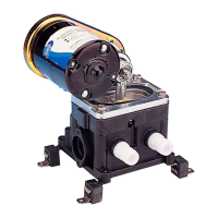
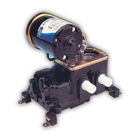
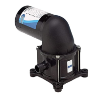
Key characteristics of the bilge pump, including self-priming, dry-running, and corrosion resistance.
Technical details on flow rate, vertical dry suction lift, ports, and weight for the pump.
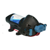
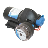
Lists available pump models (36680-2000, 36680-2010) with voltage and nominal amperage.
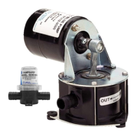
Guidance on pump mounting, plumbing connections, intake/discharge hose selection, and wiring.
Recommendations for wire gauge and fuse/breaker size based on wire length.
Instructions for winter storage, including draining and running the pump dry.
Diagram illustrating the pump components and their assembly.
Detailed list of pump components with part numbers and quantities.
Troubleshooting common problems like loss of suction and noisy operation.
Step-by-step instructions for removing, cleaning, and installing pump valves.
Procedure for replacing the diaphragm and connecting rod assembly.
Instructions for removing and replacing the pulsation dampener.
| Series | 36680-2 |
|---|---|
| Material | Polypropylene |
| Self-Priming | Yes |
| Impeller Material | Santoprene |
| Pump Body | Polypropylene |
| Voltage | 12V DC |
| Motor Type | Permanent Magnet |
| Max Temperature | 140°F (60°C) |