3
3
Ifthetoiletisplumbedtoanoverboarddischarge,andis
belowthevessel’swaterline,thedischargeplumbingmust
includeaproperlypositionedventedloop.Theventedloop
fittingmustbe securedin a locationthat remainsatleast
6-8inches(15-20cm)abovethewaterlineatallanglesof
heel and trim. The maximum discharge head without a
notabledecreaseinpumpperformanceisfourfeet(1.3M).
Ensure each hose end is pushed completely onto its
portfittingandsecureeachwithahoseclamp.Allhose
connections made below the waterline should be
secured with two stainless steel clamps. It is best to
securethehosesinplaceabouteveryeighteeninches
alongthelengthoftherun.
Onceallhoseconnectionsarecompletedandsecured
withclamps,itisbesttocompletethewiringsothetoilet
can be tested for leaks prior to fastening it to its
mountingsurface.Oncetheelectricalwiringiscomplete,
testthetoiletbyflushingseveraltimesandblotallhose
termination’scompletelyaroundeachconnectionwitha
whitepapertowelandinspectthetowelforwetspots.If
thetowelcomesawaydryfromeachconnectionwithin
the china bowl, proceed to fasten the toilet to its
mountingsurface.
Positionthetoiletinitsintendedmountingpositionand
verygently,witha10mmwrench,screwtheprovided
toilet hold-down fastener into the pilot hole drilled
earlier.Donotovertightenthesefastenersasthismay
crack the china. It is only necessary to make the
fastenerssnugenoughtopreventthetoiletfromsliding
around. Screw the dress cap into the top of the hold-
downscrew.
ELECTRICAL
Theelectricalwiringshouldbeindependentofallother
accessories. It should be made with marine grade
copper stranded wire of the gauge specified in the
electricalspecificationschart.Makeallwireconnections
with mechanical locking type connectors (crimp type
buttconnectorsandterminals).
Ensurethecircuitisprotectedbyapropersizedfuseor
circuit breaker determined from the electrical
specificationschart.Secureallwirestoasolidsurface
approximatelyeveryeighteeninches(1/2M)alongtheir
entirelengthofrun.
ELECTRICAL SPECIFICATIONS
AMP FUSE WIRE SIZE PER FEET OF RUN*
VOLTAGE DRAW SIZE
0'-10' (0 M-3 M) 10'-15' (3 M-4,6 M) 15'-25' (4,6 M-7,6 M) 25'-40' (7,6 M-12,2 M) 40'-60' (12,2 M-18,3 M)
12Vdc 10 25 #16(1,5mm
2
) #14(2,5mm
2
) #12(4mm
2
) #10(6mm
2
) #8(10mm
2
)
24Vdc 5 15 #16(1,5mm
2
) #16(1,5mm
2
) #16(1,5mm
2
) #14(2,5mm
2
) #12(4mm
2
)
*Lengthofrunistotaldistancefrompowersourcetoproductandbacktoground.
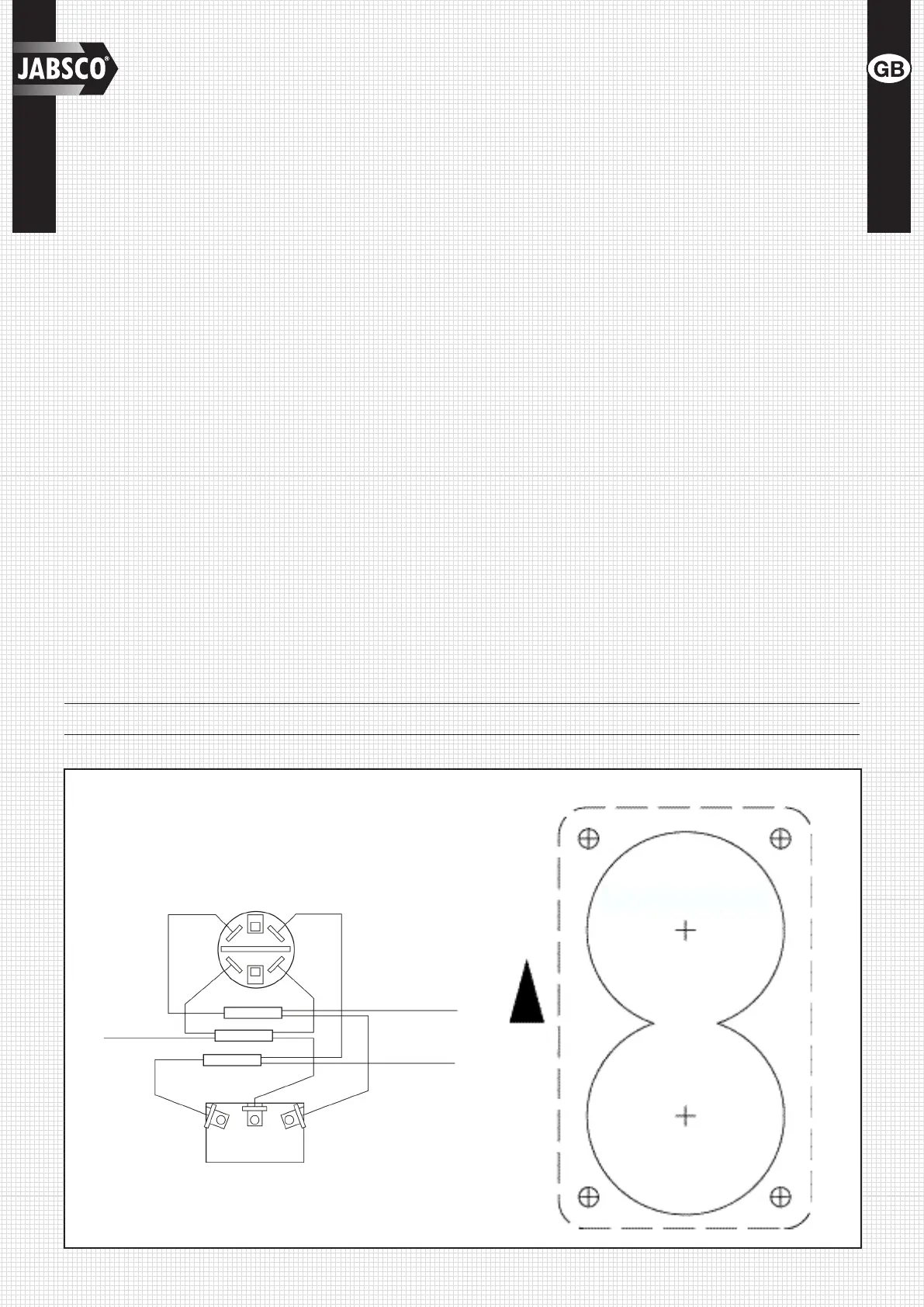
BROWN YELLOW
BROWN
YELLOW
YELLOW
BROWN
RED
RED
RED
RED
TO
POSITIVE
To Waste Pump
Positive
(Orange) Motor
Lead
To PAR-MAX
Pump Positive
(Orange) Motor
Lead
WIRING DIAGRAM TEMPLATE
1-3/4" (45 MM) DIA
1-3/4" (45 MM) DIA
UP
 Loading...