EasyManua.ls Logo

Jack F4 - User Manual

Jack F4
6 pages
Print Icon
To Next Page IconTo Next Page
Loading...
Question and Answer IconNeed help?

Do you have a question about the Jack F4 and is the answer not in the manual?

Summary

Machine Installation and Setup

Oil Pan Installation

Details on installing the oil pan, holder, and cushion on the stand.

Lubrication Information

Filling the oil pan, checking oil level, and ensuring lubrication is adequate.

Face Plate Oiling Method

How oil is supplied to the face plate parts via the main shaft plug.

Thread Management and Tension

Threading the Machine Head

Instructions on how to thread the sewing machine head.

Needle Thread Tension Adjustment

Adjusting needle thread tension using the tension nut.

Bobbin Thread Tension Adjustment

Adjusting bobbin thread tension using the tension adjust screw.

Thread Take-Up Spring Adjustment

Adjusting the stroke and tension of the thread take-up spring.

Operational Adjustments and Alignment

Needle and Hook Relation

Ensuring correct alignment between the needle and hook for proper stitching.

Pedal Pressure and Stroke Adjustment

Adjusting pedal pressure and stroke for optimal operation.

Knee Lifter Height Adjustment

Adjusting the knee lifter height for the presser foot.

Safety and Precautions

Before Operation Precautions

Crucial steps to take before operating the machine.

Operation Precautions

General precautions to follow during machine operation.

Machine Specifications

Specifications

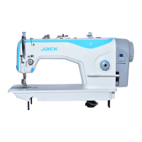
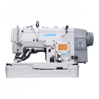
Technical specifications of the sewing machine.

Servo Motor Operation Guide

Preface and Safety Instructions

Read manual carefully before operating; operation by trained staff only.

Installation of Speed Governor

Ensuring the governor rod is perpendicular to the pedal for proper function.

Operation Panel Interface

Parameter Adjustment (Speed)

Adjusting sewing speed via the '+' or '-' buttons on the control panel.

Needle Position Adjustment

Setting the needle's stop position (up or down) using the control panel.

Control Box Error Handling and Reset

Factory Defaults Reset

Resetting control box parameters to factory defaults to resolve errors.

Error Solving with One Button

Using buttons to identify and potentially resolve error codes displayed.

Operation Requirements

Environmental and operational requirements for the control box.

Maintenance and Troubleshooting

Power Control Box Issues

Troubleshooting no reaction from the power control box, checking fuses.

Motor Not Working

Diagnosing why the motor doesn't work when the pedal is pressed.

Motor Stop Issues

Troubleshooting the motor not stopping correctly without operation.

Fuse Burning Issue

Addressing the problem of the fuse burning immediately after turning on.

Error Code List

List of error codes, their reasons, and recommended solutions.

Overview

The device is an energy-saving servo motor designed for industrial sewing machines, aiming to enhance efficiency and provide precise control over sewing operations. It is accompanied by a user manual that outlines its installation, operation, and maintenance procedures.

Function Description:

The energy-saving servo motor serves as the primary power unit for sewing equipment, offering variable speed control and needle positioning capabilities. Its core function is to drive the sewing machine with optimized energy consumption, reducing operational costs compared to traditional motors. The motor integrates a control box with a digital display and adjustment buttons, allowing users to set parameters such as speed and needle position. It supports both bottom and up needle positions, which are crucial for various sewing tasks, enabling precise fabric handling and stitch formation. The system is designed to provide stable power and consistent performance, even under varying load conditions. It also incorporates safety features, including protection against over-voltage and under-voltage, and a machine head protection safety switch to prevent damage during operation. The motor's ability to maintain a specific needle position (up or down) at the end of a sewing cycle significantly improves workflow and reduces manual adjustments.

Usage Features:

The servo motor is designed for ease of use and precise control.

  • Speed Adjustment: Users can easily adjust the motor speed using the "+" and "-" buttons on the control panel. The display shows the current speed in revolutions per minute (rmp/min), with a typical range up to 3500 rmp/min. This allows operators to match the sewing speed to the specific fabric and task requirements, from delicate work to high-speed production.
  • Needle Position Adjustment: The device offers a needle position adjustment feature, allowing the operator to set whether the needle stops in the up or down position when the pedal is released. This is particularly useful for pivoting fabric or ensuring the needle is in the correct starting position for the next stitch. The adjustment is made by pressing the "+" button for three seconds and then setting the desired position.
  • Parameter Reset: In cases of abnormal operation or incorrect parameter settings, the system allows for a factory default reset. This can be initiated by pressing the "-" button for three seconds when the panel shows "P," and a successful reset is indicated by "OK" on the display. This feature helps in troubleshooting and restoring the device to its optimal default configuration.
  • Error Code Display: The control panel displays error codes (e.g., E1, E2, E4, E5, E6, E7, Eb, Ec, OF) to indicate specific issues, such as motor stuck, controller abnormal, needle position abnormal, speed governor abnormal, over-voltage, or under-voltage. This diagnostic capability helps operators identify and address problems quickly, minimizing downtime.
  • One-Button Error Solve: For certain error codes, the system provides a one-button solution, where pressing a specific button on the panel can help resolve the issue or guide the user to the relevant error code for further action.
  • Standby Mode: The motor enters a standby mode after about 30 minutes of inactivity, indicated by the "OF" error code, to conserve energy. It can be reactivated by pressing the "+" or "-" button.
  • Installation of Speed Governor: The manual provides detailed instructions for installing the speed governor, ensuring the rod position is perpendicular to the pedal and the pedal angle relative to the ground plane is approximately 15 degrees for optimal ergonomic use.

Maintenance Features:

The manual emphasizes several maintenance and troubleshooting aspects to ensure the longevity and reliable operation of the servo motor.
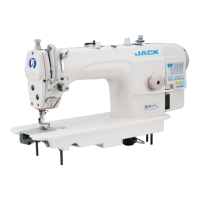
  • Professional Maintenance: It is strongly recommended that maintenance and operation be performed by professionally trained personnel, especially when the machine malfunctions.
  • Power Connection Check: In case of no reaction upon power-on, users are advised to check the power plug connection and the fuse. Instructions are provided for locating and replacing a burnt fuse with one of the same type.
  • Speed Controller Check: If the motor doesn't work when the pedal is pressed, users should verify the connection of the speed controller and check if it is broken.
  • Motor Stop Issue Troubleshooting: If the motor cannot stop operating, users are guided to check the position of the magnetic steel coil. The manual explains how to open the speed governor, adjust the plastic rocker arm, and ensure the magnetic steel coil is correctly aligned with the Hall sensor.
  • Fuse Burning Issue: If the fuse burns immediately after turning on the machine, even after replacement, users are advised to contact the local agent for repair, indicating a potentially more serious underlying issue.
  • Environmental Requirements: The manual specifies operational requirements, such as avoiding magnetic or high-radiation environments, maintaining an ambient temperature between -5°C and 40°C, and keeping the device away from heaters, wet conditions, corrosive substances, and explosive atmospheres. Adequate ventilation is also crucial for the control box and motor.
  • Power Supply Stability: Maintaining a steady power supply voltage is essential for the device's proper functioning. The system includes protections against over-voltage (above 264V) and under-voltage (below 154V), prompting users to adjust the voltage or change parameters if these conditions occur.
  • Grounding: The system must be properly grounded to ensure safety during operation.
  • Error Code Solutions: The manual provides a comprehensive list of error codes with corresponding reasons and solutions, guiding users through troubleshooting steps for common issues like motor stuck, controller abnormalities, and sensor problems. For persistent errors, contacting the manufacturer is recommended.
  • Structural Integrity: Users are explicitly warned against altering the structure or any motor parts, as this could lead to customer responsibility for any resulting damage.

Jack F4 Specifications

General IconGeneral
BrandJack
ModelF4
CategorySewing Machine
LanguageEnglish

Related product manuals