4
INSTALLATION MANUAL FOR 490A
Section 2: Engine Preparation
Clean engine thoroughly. Remove engine valve cover
and gasket. Retain all parts.
Crosshead and Adjusting Screws
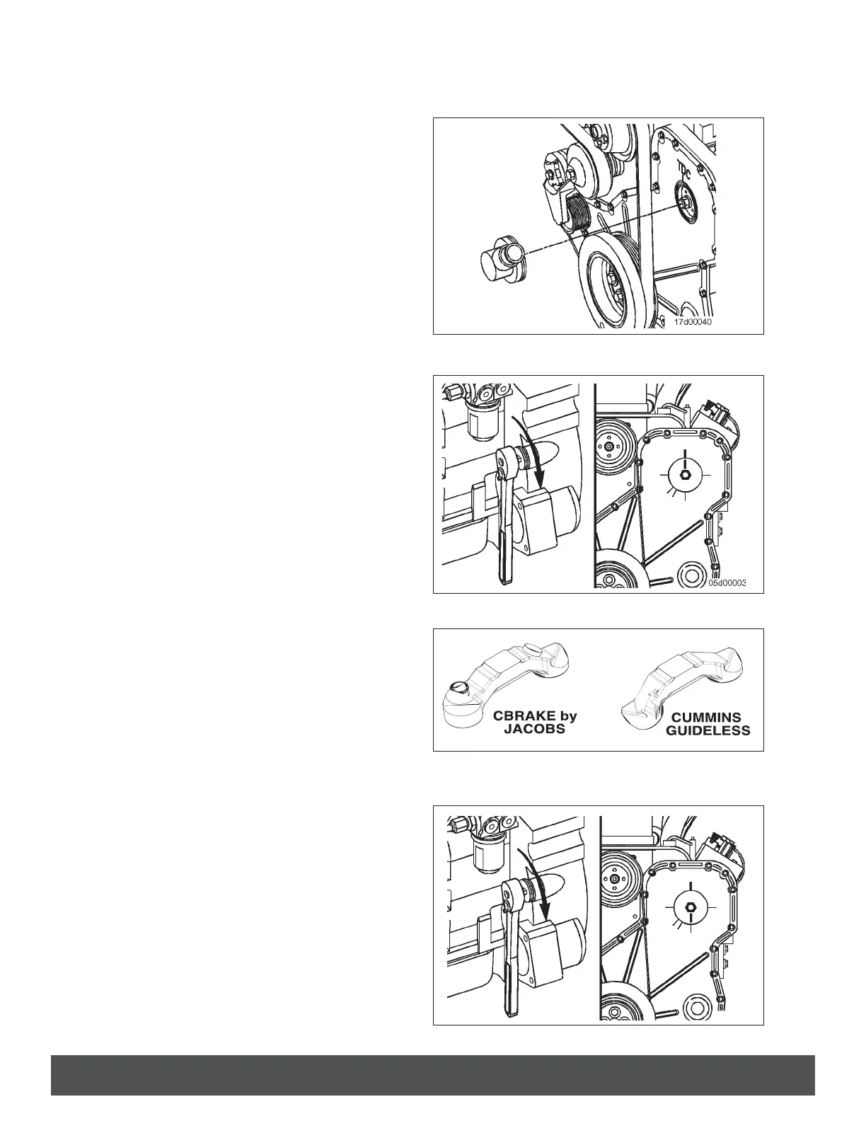
1. Remove the plastic pump drive cover located on
the front of the engine. This will expose the fuel
pump gears and timing marks (Fig. 1).
2. Using the barring tool, Part No. 5299073, rotate
the crankshaft to align the mark on the fuel
pump gear with the top dead center mark on the
gear cover (Fig. 2).
3. Remove Intake rocker lever mounting studs on
cylinders 1 and 4. Replace with new engine
brake oil supply studs. Torque to 60 N•m [45 ft-
lb].
4. Adjust intake lash on cylinders 1, 2, and 4.
NOTE: REFERENCE ENGINE MANUAL FOR INSTRUC-
TION ON SETTING INTAKE VALVE LASH.
5. Remove exhaust rocker lever mounting studs on
Cylinders 1, 3, and 5.
6. Remove exhaust crossheads and replace with
CBrake by Jacobs
®
Crossheads (Fig. 3).
7. Install new exhaust rocker lever mounting studs
(these will accept the engine brake mounting
bolts). Torque to 60 N•m [45 ft-lb].
8. Remove exhaust rocker adjusting screw locknut
on cylinders 1,3, and 5. Replace lock nuts with
longer lock nut provided in the kit. Do not tighten
at this time.
9. Adjust the exhaust valve lash on cylinders 1, 3,
and 5. Tighten locknut to 25 N•m [20 ft-lb]. In-
stall spherical nut onto long lock nut and torque
to 40 N•m [30 ft-lb].
NOTE: REFERENCE ENGINE MANUAL FOR INSTRUC-
TION ON SETTING EXHAUST VALVE LASH.
10. Check exhaust valve lash on cylinders 1, 3, and
5. Adjustment may have moved when torquing
the spherical nut. Readjust as necessary.
11. Using the engine barring tool, Part No.
5299073, rotate the crankshaft 360 degrees
to align the mark on the fuel pump gear with
the mark on the gear cover that is 180 degrees
away from top dead center (Fig. 4).
12. Adjust intake lash on cylinders 3, 5, and 6.
NOTE: REFERENCE ENGINE MANUAL FOR INSTRUC-
TION ON SETTING EXHAUST VALVE LASH.
FIG. 1
FIG. 2
FIG. 4
FIG. 3