GB-23
JACOBSEN G-PLEX III Series: DN & DP
MAINTENANCE AND PARTS MANUAL
GB
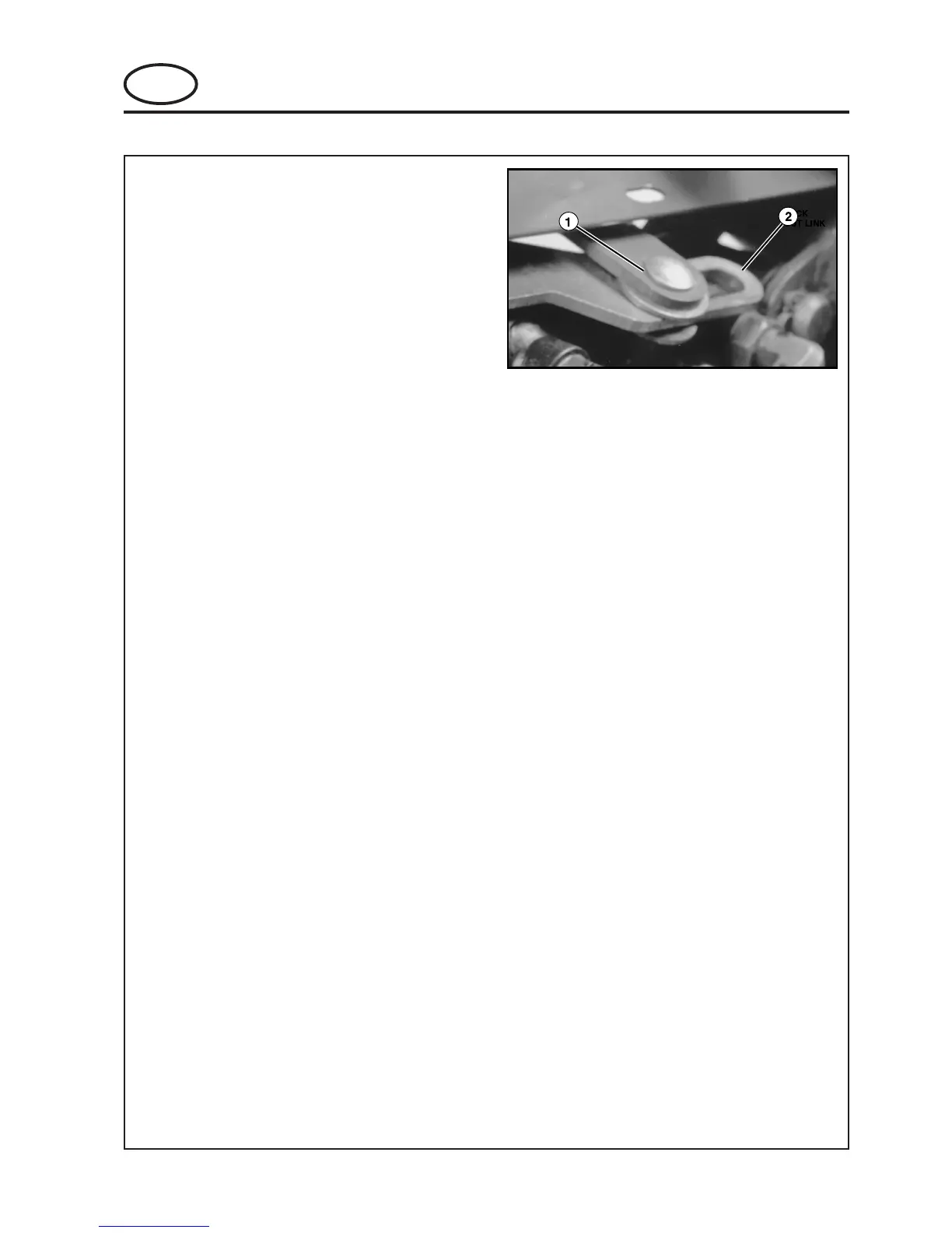
Figure 6.3.4
Position Bushing to Left of Slot
Rotate bellcrank clockwise (as viewed from above)
and hold the bushing on the lockout link angle to the
left end of the lockout link slot (See Fig. 6.3.4).
Slide the bellcrank stop screw to the left of the slot
located in the foot panel (See Fig. 6.3.2) making
sure the bellcrank contacts the stop screw.
With the screw held tightly against the bellcrank,
tighten the stop screw nut.
Install the center foot panel.
6 ADJUSTMENT
 Loading...