GB-22
GB
JACOBSEN G-PLEX III Series: DN & DP
MAINTENANCE AND PARTS MANUAL
6.3 SPEED CONTROL PEDAL
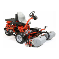
Figure 6.3.1
1. Mow Speed Adjustment Screw
2. Locking Nut
Figure 6.3.2
1. Bellcrank Stop Screw
2. Center Foot Panel
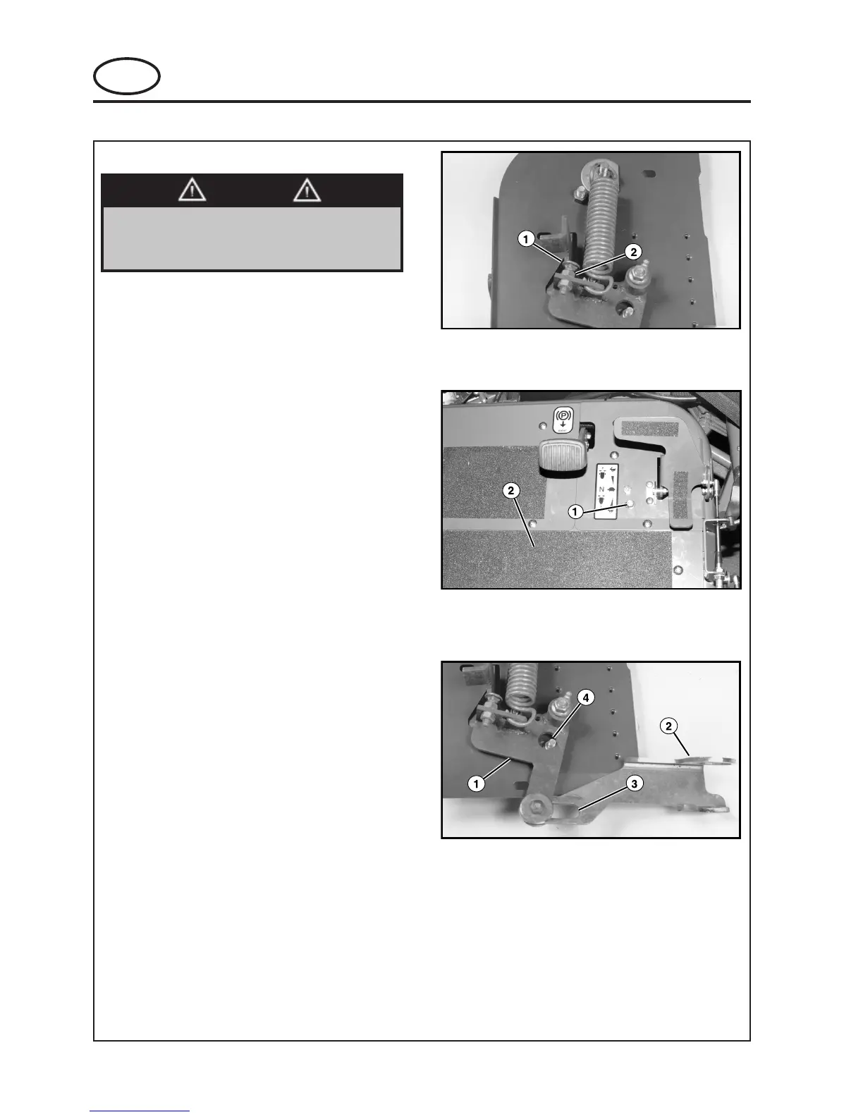
Figure 6.3.3
1. Bellcrank
2. Lockout Link Angle
3. Lockout Link slot
4. Bellcrank Stop Screw
This procedure MUST be performed as
specified and only by properly trained
service personnel.
WARNING
Adjusting the speed control screw out (increasing
length) will reduce the mow speed. Adjusting the
speed control screw in (shortening length) will
increase mow speed.
Determine which direction to adjust the mow speed
screw. Loosen the locking nut and adjust speed
control screw, snug up the locking nut and run the
time test again, repeat as necessary. When correct
mow speed has been obtained, tighten the locking
nut (See Fig. 6.3.1).
TO SET BELLCRANK STOP SCREW:
NOTICE
The bellcrank stop screw has been set at the factory
and should NOT require adjustment. If stop screw is
loosened or removed, it MUST be properly installed
and adjusted prior to unit operation.
Remove the screws securing the center foot panel
and remove panel (this will allow access to the
lockout link angle).
Loosen the nut on the bellcrank stop screw just
enough to allow the screw to be slid to the left of the
slot (See Fig. 6.3.3).
6 ADJUSTMENT
 Loading...