73
Collegamenti sulla scheda elettronica/impostazione dei “dip switch”
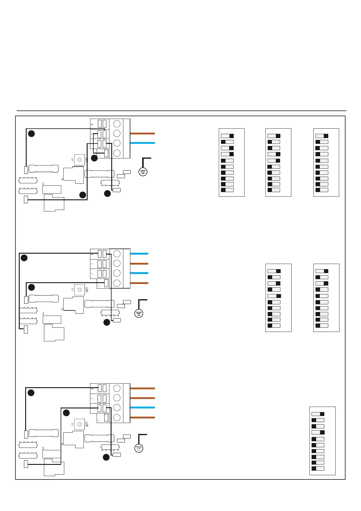
A seconda del numero di linee di alimentazione predisposte eettuare i collegamenti tra i connettori e congurare il banco-interrut-
tori “dip-switch” come indicato:
Electronic board connections/Setting the dip switches
According to the number of power lines, connect the connectors up and congure the dip switches as indicated:
Raccordements sur la carte électronique/conguration des « dip switch »
Selon le nombre de lignes d'alimentation prévues, eectuer les raccordements entre les connecteurs et congurer le bandeau des
interrupteurs « dip-switch » comme indiqué :
N1
N2
L1
L2
GRN
A
B
C
D
P1 2SPD
UV
A/V
30A (PMP 1)
30A (PMP 2)
J33
J36 J53
J41
J46
J47
J51
J59
J38
J44
F4
F6
J35
J37
GRN
A
B
C
D
P1 2SPD
UV
A/V
30A (PMP 1)
30A (PMP 2)
J33
J36
J53
J41
J46
J47
J51
J59
J38
J44
F4
F6
J35
J37
G-GRN
A
B
C
D
P1 2SPD
UV
A/V
30A (PMP 1)
30A (PMP 2)
J33
J36
J53
J41
J46
J47
J51
J59
J38
J44
F4
F6
J35
J37
3,5kW
5,1kW6,7kW
6,7kW
3,9kW
1: J33 ---> J47
2: J59 ---> J41
3: J37 ---> J36
4: J46 ---> J51
1: J33 ---> J51
2: J59 ---> J38
3: J37 ---> J53
1: J38 ---> J51
2: J59 ---> J41
3: J37 ---> J36
1
2
3
4
5
6
7
8
9
10
ONOFF
1
2
3
4
5
6
7
8
9
10
ONOFF
1
2
3
4
5
6
7
8
9
10
ONOFF
5,1kW / 6,7kW
1
2
3
4
5
6
7
8
9
10
ONOFF
1
2
3
4
5
6
7
8
9
10
ON
OFF
1
2
3
4
5
6
7
8
9
10
ONOFF
4
2
2
1
1
3
3
2
3
1
N1
L1
N1
L1
L3
L2

 Loading...