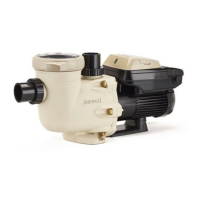
Page 27 of 32 IS3206VSP3J Rev-A
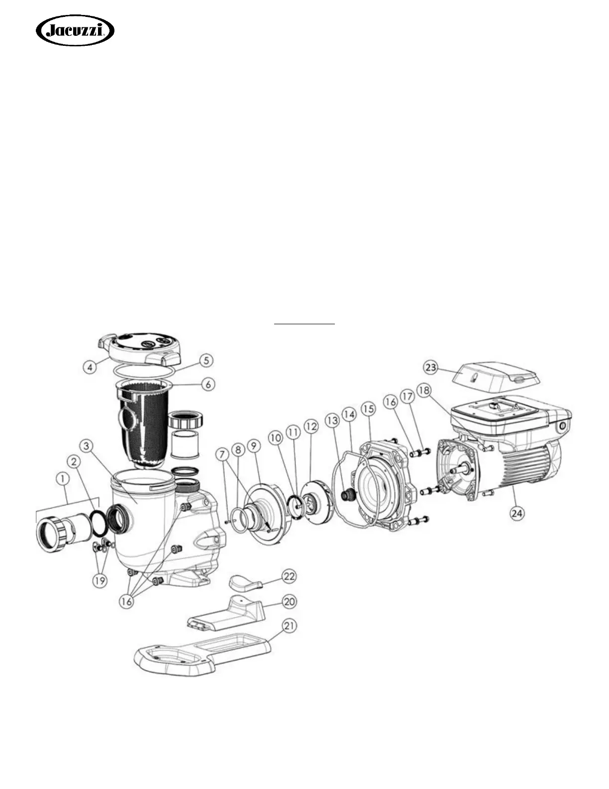
9.5. Replacing the Impeller and Diffuser
11. Screw the impeller (item #12) onto the motor shaft in a clockwise direction, and screw the impeller screw (item #10)
into the motor shaft in a counterclockwise direction. Tighten snugly by holding motor shaft with wrench as noted in
step #4. Place the impeller ring (item #11) back onto the impeller (item #12), with flange facing towards the diffuser
(item #9).
12. Place the diffuser (item #9) over the impeller (item #12) and onto the seal plate (item #15), aligning the three pins on
the diffuser (item #9) with the three holes on the seal plate (item #15). Replace the two diffuser screws (item #7).
9.6. Replacing the Motor Assembly
13. Slide the motor assembly, with the diffuser (item #9) in place, into pump/strainer housing (item #3), being careful not
to disturb the diffuser gasket (item 8)
14. Fasten assembly to pump/strainer housing (item #3) using the six (6) 5/16" x 2" bolts (item #17). (Be sure housing
gasket (item #14) is in place, and lubricated. Replace if damaged). Tighten bolts alternately and evenly to 185 inch-
pounds according to housing bolt torque pattern detail.
10. Replacement Parts
10.1. Parts Diagram
Figure 10.1-1