RAC Plus User’s Manual
2-4
2-5
Chapter 2 — Installation
is switched off with the ignition key.
We also recommend the circuit should
have as few devices as possible to avoid
voltage uctuations from Turn Signals,
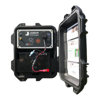
Brake Lights, etc. Plug the power cable
into the hole labeled Power on the
MDS, as shown in Figure 2.4.
A diagram of the complete installation for the MDS is shown in Figure 2.6
on page 2-6.
Adjusting the Vehicle Speed Sensor Pulse Rate
The signal pulses coming from the vehicle speed sensor are generated for use
by the vehicle’s computer, engine/transmission control, fuel management,
ABS brakes, etc. The pulse rate can vary from 4,000 to in excess of 100,000
pulses per mile. The MDS will condition and amplify these pulses for use by
the DMI. Since the higher pulse rates
are not required for accurate distance
measurements, the MDS incorporates a
divider circuit to reduce the pulse rate.
This is done by adjusting the rotary
switch on the front of the MDS, as
shown in Figure 2.5.
Although your particular vehicle may
vary, generally Chrysler and Ford vehicles use a 4 to 1 ratio (position 4 on
the switch) while General Motors vehicles use a 16 to 1 ratio (position 16 on
the switch). To adjust the ratio, use a small screwdriver to rotate the switch
until the slot in the switch points to the desired ratio. Note that when the
switch is turned counter-clockwise until it stops, it is at the 1 to 1 ratio.
The adjustments go from 1 to 1 (1 pulse into the sensor, 1 pulse out) through
64 to 1 (64 pulses into the sensor, 1 pulse out). The Tap Test positions
are explained in the troubleshooting section on page 3-4. You may need
to adjust the ratio again based on the results of the calibration procedure
described in Chapter 3. Any time you change the pulse ratio, you will need
to re-calibrate the DMI.
Once you have installed the MDS, install your RAC Plus using the instruc-
tions on page 2-7.
Fig. 2.4 –Power Plug-in
Fig. 2.5
Rotary Switch Adjustment