7
8. Explosion Protection – Device Description
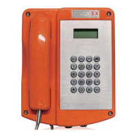
Regarding the explosion protection the JREX106 telephone and the JREX106-CB telephone version are identical.
The explosion protection enables the user to make and receive calls within hazardous areas of zone 1, zone 2, zone 21, zone 22, in presence of an
explosive gas or dust atmosphere.
The JREX106 telephone is manufactured in the following protection classes:
II 2G Ex e [ib] mb IIC T6 Gb
II 2D Ex tb [ib] IIIC T85 °C Db
-40°C ≤ Ta ≤ +70°C
The JREX106 telephone is designed for connection with analogue telephone networks.
The non-intrinsically safe voltage of the telephone network is connected to the terminals in increased safety. In calling / ringing mode, this voltage is
switched to the terminals in increased safety. The terminals (Bell shunt1, Bell shunt) are intended for passive consumers, e.g. a passive external,
explosion-proof secondary ringer.
Furthermore,a non-intrinsically safe voltage from the analogue telephone network is turned into:
• an intrinsically safe receiver circuit with terminals on the inside of the telephone housing, for use with the receiver,which is permanently connected
to the telephone housing, and
• intrinsically safe circuits with terminals within the telephone housing for connecting an intrinsically safe headset or, optionally,an intrinsically safe
second earpiece, and
• an intrinsically safe circuit with terminals within the telephone housing for the connection of an intrinsically safe loudspeaker.
The accessories headset, second earpiece, external loudspeaker and external secondary ringer are not parts of the JREX106 telephone, but
optional extras.
9. Assembly and Installation
The telephone must be installed on a plane surface in vertical operating position only. Loosen the cover screws and detach the upper part of the
telephone. If the optional accessory headset is being employed, attach the bracket using two screws to the rear panel of the lower part of the telephone.
(With the accessories named before, the bracket and screws are in the scope of delivery. With all accessories a cable gland is delivered).
Put four screws, having a head diameter of 10 to 13 mm into the holes and attach the lower part of the telephone to the wall or to a holder. Guide the
telephone wire through the cable gland and place it on the terminals. Only wires having a sheath diameter of 5.5 to 13 mm should be used because
otherwise the IP67 housing protection standard is not guaranteed. Prior to assembly, check cover seal for tightness.
Using the plug connector, plug the ribbon cable onto the pin contact strip in the upper part of the housing. Attach the upper part of the telephone and
fasten it to the lower part of the telephone with the four cover screws. Upon disassembly of optional accessories, suited sealing plugs must be used to
close the resulting openings. In this telephone connected cords may have hazardous voltages. To ensure that no water gets into the enclosure it is
essential that no gaskets are damaged during installation. The ingress of water can cause accessible parts of the telephone to become live.
The locking torque of the upper part screws is: 1.2 …1.5 Nm. Installation and connection must be carried out by competent personnel familiar with electrical
and network installation.

 Loading...