Page 58
Jandy
®
JXi
™
Gas-Fired Pool and Spa Heater | Installation & Operation Manual
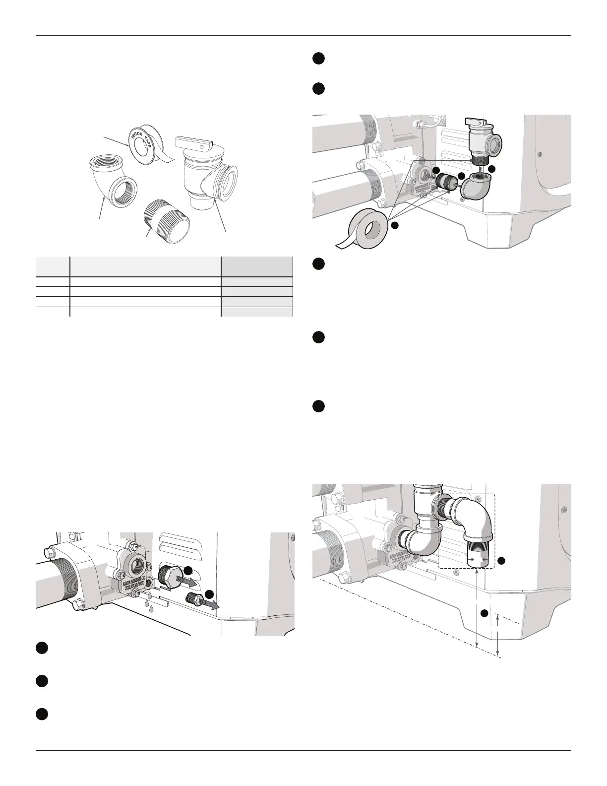
13.3.2 Install Pressure Relief Valve kit #R0336102
Please double check that you have all necessary
parts to complete the installation. If any parts are
missing or damaged please call 1-800-822-7933 for
assistance.
1
2
3
4
ITEM Description Bronze Header
1 Pressure Relief Valve 3/4” X 3/4” 75 PSI X
2 Brass Nipple 3/4” X
3 Elbow 90° 3/4” NPT Brass X
4 Tefl on Tape X
Prior to installing or replacing this pressure relieve
valve (PRV), ensure the following steps have been
completed.
• Turn off the electrical power to the heater.
• Turn off the main gas supply to the heater.
• If the heater has been operating, ensure you
allow enough time for remaining water in the heat
exchanger to cool down before beginning. It is
recommended that protective gloves be worn
during the entire procedure.
• Make sure the fi lter pump is off and will remain off
for the duration of the installation procedure.
• If the heater is below the surface level of the
water in the pool or spa, close all shut-off valves
between the heater and the pool.
a
b
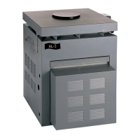
Remove drain plug from header and allow all
water to drain from heat exchanger.
Remove the port plug on Thermal Regulating
Valve access plate.
Each male connection should be fi rst wrapped in
5-6 turns of Tefl on
™
tape.
d
Assemble the 3/4” threaded nipple and elbow.
Make sure to get a sung fi t. Do not overtighten.
Install the nipple and elbow assembly at the
access plate port.
f
c
e
d
Install the pressure relief valve. Make sure to get
a sung fi t. Do not overtighten.
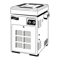
The fi nal orientation of the pressure relief valve
should be vertically aligned with the discharge
opening facing away from the heater header.
Install a discharge pipe from the pressure relief
valve discharge opening to a safe area. This is a
precaution to prevent the possibility of personal
injury or property damage in the event scalding
water is discharged from the pressure relief valve.
h
Install the discharge pipe so that there is no
trapped or standing water in the piping. Discharge
piping must be facing down, terminating with a
threadless nipple, no more than 6 in (152 mm) and
no less than twice the diameter of the discharge pipe
from the fl oor or drain/receptor..
g
h
Threadless Discharge Pipe
Ground Level
6 in (152 mm) Max
2 X (Øa) Min.
Øa
*
*Not supplied by Zodiac
To ensure the continued proper operation of the
pressure relief valve, the valve should be tested
once a year. To test, lift the lever with the circulation
system running to ensure that water will pass
through. When the lever is down, there should be no
leaks from the outlet.