Page 14
1. For an existing installation, drain the heater by
removing the drain plug on the inlet/outlet header
and the two drain plugs on the return header.
2. Remove the heater front panel (door).
3. Remove the two hex head screws that hold the
raceway cover in place. They are located on the
bottom flange of the raceway cover. Slide the
raceway cover down to expose the raceway.
4. Remove the control panel assembly from the top
panel (see figure 13 for panel identification). Lift
the control panel cover. Remove the two philips
head screws located at the front edge of the
bezel. Lift the front of the bezel up until the entire
assembly comes away from the top. Without
removing any wires, slip the control assembly
through the hole so that when the top is removed,
the control assembly will stay with the heater.
5.4 Reversible Water Connections
The LX and LT Low NOx heaters are shipped
with water connections on the right side, but they can
be modified in the field to provide left-side water
connections. This procedure involves removing the
heat exchanger headers and reinstalling them on
opposite ends of the tube assembly. Some of the
heater wiring and control components must be relo-
cated, so this procedure must be done only by a trained
service technician.
Heat exchanger reversals are generally done
before the installation of power and water to the
heater. If you need to reverse the heat exchanger on a
previously installed heater be sure that all electrical
power, the gas supply and water supply have been
turned off before starting the procedure. These
instructions have been written to include the steps
needed when reversing the water connections on an
existing installation. If you are reversing the headers
on a new installation, some steps will be ignored.
Water connection reversal is illustrated in Figures 11
and 12 . Proceed as follows:
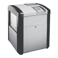
Figure 11. Water Connections as Shipped
Figure 12. Water Connections Reversed
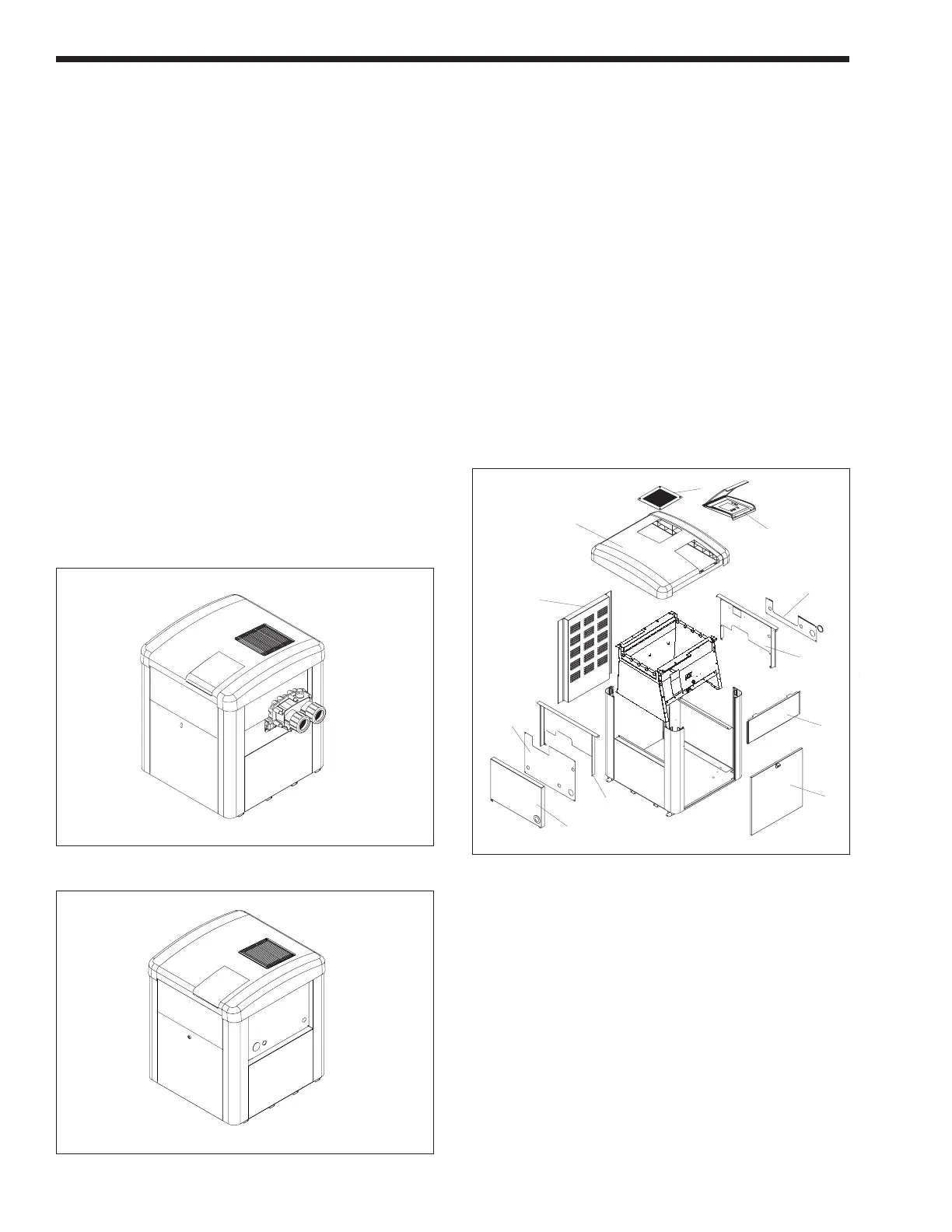
Figure 13. LX/LT Panel Identification
I/O HEADER SIDE
COVER PLATE
UPPER
RIGHT SIDE
PANEL
UPPER
LEFT SIDE
PANEL
RETURN
HEADER SIDE
COVER PLATE
LEFT
SIDE COVER
PANEL
REAR
PANEL
TOP
PANEL
CONTROL
PANEL
GRILL
FRONT
PANEL
(DOOR)
RACEWAY
COVER
5. Remove the four philips head screws that fasten
the vent grill to the top. Remove the vent grill.
6. Remove the top. Remove the two hex head
screws at the upper corners of the raceway.
Now lift up on the front of the top and push it
toward the rear of the heater. The top will slide
off the heater.
7. Remove the water pressure switch's copper
siphon loop tube from the header by first loosen-
ing the brass nut at the pressure fitting. Then
carefully pull the tube out of the fitting. There
should be about two inches of tubing inside the
header. Be careful not to create any kinks in the
tubing when handling it.