LX and LT Low NOx Pool/Spa Heater Page 17
5.6 Pressure Relief Valve
A pressure relief valve (PRV) is recommended
in all installations, and is mandatory in any installation
in which the water flow can be shut off between the
heater outlet and the pool/spa.
A pressure relief valve is not supplied with the
LX and LT Low NOx heaters. However, it is recom-
mended that a pressure relief valve be installed and
may even be required by local codes. Be sure to check
any applicable installation codes in your area to
determine whether a pressure relief valve is required.
The pressure rating of the valve should be at or
below the lowest working pressure of any component
in the system. Any pressure relief valve installed must
comply with provisions of the standard described in
ANSI Z21.22 for the United Sates of CSA 4.4 in
Canada.
Follow these steps to install a pressure relief valve.
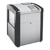
1. To protect the threads while drilling, screw the
brass adapter (included with the Jandy PRV kit)
into the blind threaded hole on the top of the inlet/
outlet header.
2. Using the countersink in the center of the blind
hole as a guide, drill a 1/4 inch hole through the
plastic (see Figure 16).
3. Open the hole by reaming it with a 3/8 inch drill
bit.
4. Open the hole again by reaming it with a 1/2 inch
drill bit.
CAUTION
Initially drilling a 1/2" hole without reaming may
cause the bit to "grab" on the plastic. This may
cause personal injury or damage the plastic
header.
ATTENTION
Si vous commencez à percer le trou de ½’’
sans alésage préalable, la mèche risque de «
mordre » dans le plastique. Vous risquez de
vous blesser ou d’endommager le tuyau
collecteur de plastique.
5. Remove the brass adapter and clean the cuttings
out of the hole.
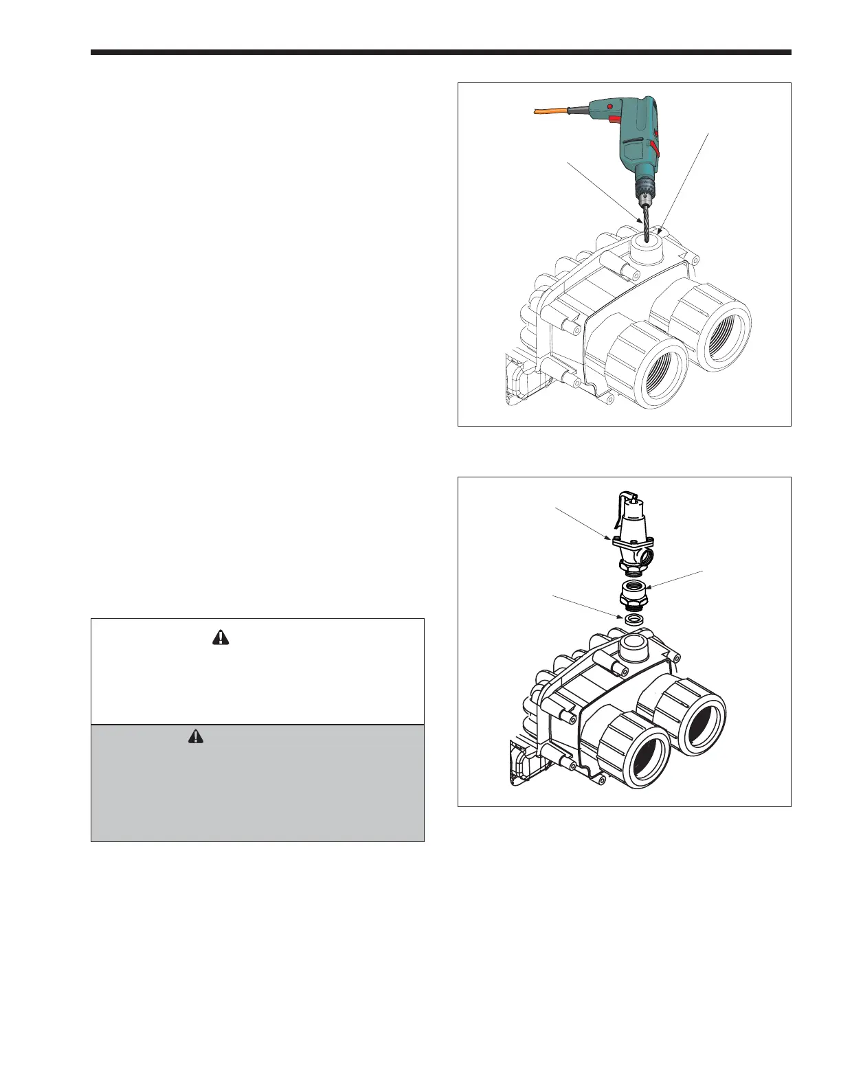
6. Install the rubber washer at the bottom of the
hole (see Figure 17).
7. Thread the adapter into the hole and tighten so
that it seals against the rubber washer.
8. With a permanent marker, place a mark on the
adapter so that the mark faces the same direction
as the water connections on the header.
9. Remove the adapter from the hole.
10. Coat the threads of the pressure relief valve
(PRV) with an appropriate metal to metal thread
sealant.
11. Install the adapter on the PRV and tighten using
two wrenches. Use the mark made earlier on the
adapter to orient the PRV to the desired direction
in relation to the water connections on the
header.
Figure 17. Pressure Relief Valve Installation
Figure 16. Drill Hole for Pressure Relief Valve
TEMPORARILY
INSTALL BRASS
ADAPTER TO
PROTECT PLASTIC
THREADS
START WITH A 1/4" BIT
THEN OPEN HOLE WITH
A 3/8" BIT THEN OPEN
HOLE WITH A 1/2" BIT
RUBBER WASHER
BRASS ADAPTER
PRESSURE RELIEF
VALVE HAND
TIGHTEN ONLY