EasyManua.ls Logo

Jarvis Buster IX - User Manual

Jarvis Buster IX
20 pages
Print Icon
To Next Page IconTo Next Page
Loading...
JARVIS
TABLE OF
CONTENTS Page............................
Buster IX Band Saw
480V, 60Hz 4006196............
415V, 50Hz 4006204............
380--400V, 50Hz 4006195.......
380V, 60Hz 4006197............
240V, 60Hz 4006209............
230V, 50Hz 4006210............
208V, 60Hz 4006220............
42V, 50Hz 4006194.............
Spring Balancer 4042023.............
Air Balancer
48 in (1219 mm) body 4042016.....
120 in (3048 mm) body 4042020....
Blades:
Standard 1023159.................
Cut Tooth 1023338................
Jet 1023620......................
Cut Tooth Jet 1023623.............
Model Buster IX
Carcass Splitting Band Saw
EQUIPMENT
SELECTION Ordering No............
Notice to Employer and Safety
Director 2...........................
Notice to Operators, Maintenance
and Cleanup Personnel 3..............
Parts Diagram and List 4..............
Part Number Table 12.................
Wiring Diagrams 13..................
Specifications 17.....................
Installation Instructions 17.............
Operating Instructions 17..............
Maintenance Instructions 18...........
®
6206026
PRODUCTS CORPORATION
33 ANDERSON ROAD, MIDDLETOWN, CONNECTICUT 06457--4926
UNITED STATES OF AMERICA E--MAIL.
jarvis.products.corp@snet.net
TEL. 860--347--7271 FAX. 860--347--6978 WWW.jarvisproducts.com
Question and Answer IconNeed help?

Do you have a question about the Jarvis Buster IX and is the answer not in the manual?

Summary

Safety and Operator Notices

Notice to Employer and Safety Director

Guidelines for employers and safety officers regarding tool safety and personnel training.

Notice to Operators, Maintenance and Cleanup Personnel

Instructions for operators, maintenance, and cleanup crews on safe tool operation and handling.

Component Identification and Diagrams

Figure A Idler End Parts Diagram

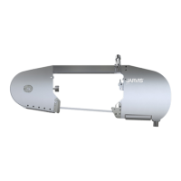
Detailed illustration of the idler end components with a corresponding parts list.

Figure B Drive End Parts Diagram

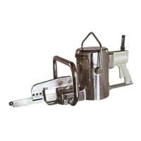
Detailed illustration of the drive end components with a corresponding parts list.

Figure C Motor and Handle Assembly Diagram

Illustration of the motor and handle assembly components with a parts list.

Figure D Blade Guide Assemblies Diagram

Illustration of the blade guide assemblies with a parts list.

Figure E Upper Trigger Handle Assembly Diagram

Illustration of the upper trigger handle assembly components with a parts list.

Figure G Rail Assembly Diagram

Illustration of the rail assembly components with a parts list.

Figure F Hanger Assembly Diagram

Illustration of the hanger assembly components with a parts list.

Figure H Torque Knob Assembly Diagram

Illustration of the torque knob assembly components with a parts list.

Figure I Wheel Assemblies Diagram

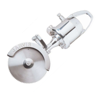
Illustrations of the drive and idler wheel assemblies with parts lists.

Figure J Gearbox Assembly Diagram

Illustration of the gearbox assembly components with a parts list.

Figure K Control Box Assembly Diagram

Diagram of the control box assembly with component labels.

Table 1 Control Box Parts

Detailed table listing parts for the control box across various voltage/frequency configurations.

Electrical Wiring Schematics

Wiring for 42 V, 3 phase, 50 Hz

Electrical wiring schematic for the 42V, 3-phase, 50Hz configuration.

Wiring for 230 V, 3 phase, 50 Hz

Electrical wiring schematic for the 230V, 3-phase, 50Hz configuration.

Wiring for 380-400 V, 3 phase, 50 Hz

Electrical wiring schematic for the 380-400V, 3-phase, 50Hz configuration.

Wiring for 415 V, 3 phase, 50 Hz

Electrical wiring schematic for the 415V, 3-phase, 50Hz configuration.

Wiring for 480 V, 3 phase, 60 Hz

Electrical wiring schematic for the 480V, 3-phase, 60Hz configuration.

Wiring for 480 V, 3 phase, 60 Hz without Door Interlocks

Electrical wiring schematic for the 480V, 3-phase, 60Hz configuration without door interlocks.

Specifications, Installation, and Operation

Machine Specifications

Technical details including motor power, voltage, capacity, dimensions, and weight.

Installation Instructions

Step-by-step guide for setting up and installing the band saw.

Operation Instructions

Procedures for safely and effectively operating the band saw.

Maintenance Instructions

Guidelines for routine cleaning, lubrication, and part checks for the band saw.

Jarvis Buster IX Specifications

General IconGeneral
BrandJarvis
ModelBuster IX
CategorySaw
LanguageEnglish

Related product manuals