EasyManua.ls Logo

Jarvis 1000-FS User Manual

Jarvis 1000-FS
16 pages
To Next Page IconTo Next Page
Page #1 background imageLoading...
Page #1 background image
JARVIS
TABLE OF
CONTENTS Page.........................
Model 1000--FS
9” Blade and Guard, Std 4007006....
9” Chine Bone 4007021.............
9” Left Side 4007033...............
10.5” Blade and Guard, Std 4007007.
10.5” Chine Bone 4007022..........
10.5” Adjustable Handles 4007049...
10.5” Left Side 4007041.............
12” Blade and Guard, Std 4007008...
12” Chine Bone 4007023............
12” Adjustable Handles 4007050.....
12” Left Side 4007035..............
380 mm Blade & Guard, Std 4007062
Hydraulic Power Unit 27--10SC 4027042
Balancer 4042004....................
Notice to Employer and Safety
Director 2.........................
Notice to Operators, Maintenance
and Cleanup Personnel 3............
Parts Diagram and List 4............
Specifications 9....................
Installation Instructions 9............
Installation Diagram 10..............
Operation Instructions 11............
Maintenance Instructions 11.........
PRODUCTS CORPORATION
33 ANDERSON ROAD, MIDDLETOWN, CONNECTICUT 06457--4926
UNITED STATES OF AMERICA
TEL. 860--347--7271 FAX. 860--347--6978
6207001:::
Model 1000--FS
Hydraulic Powered Breaking Saw
EQUIPMENT
SELECTION Ordering No..............
®
Adjustable Handles
Chine Bone
Standard Tool

Other manuals for Jarvis 1000-FS

Question and Answer IconNeed help?

Do you have a question about the Jarvis 1000-FS and is the answer not in the manual?

Jarvis 1000-FS Specifications

General IconGeneral
BrandJarvis
Model1000-FS
CategorySaw
LanguageEnglish

Summary

Safety Instructions

Notice to Employer and Safety Director

Employer responsibilities for safe tool operation and training.

Notice to Operators, Maintenance and Cleanup Personnel

Safety guidelines for users, maintenance, and cleanup staff.

Parts Diagrams and Lists

Figure A - Standard Tool Parts

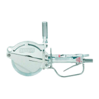
Diagram and list of parts for the standard front handle assembly.

Figure B - Rear Handle Assembly Parts

Diagram and list of parts for the standard rear handle assembly.

Figure C - Adjustable Handle Assembly Parts

Diagram and list of parts for adjustable handle assemblies.

Figure D - Hydraulic Power Unit Parts

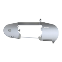
Diagram and list of parts for the electric-hydraulic power unit.

Figure E - Electrical Control Box Parts

Diagram and list of parts for the electrical control box.

Specifications and Installation

Specifications

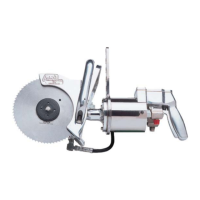
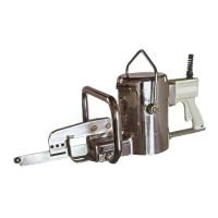
Technical data and performance characteristics of the breaking saw.

Installation Instructions

Step-by-step guide for setting up the hydraulic power unit and saw.

Installation Diagram

Visual guide illustrating the hydraulic and electrical connections.

Operation and Maintenance

Operation Instructions

Procedures for safe and effective use of the breaking saw.

Maintenance Instructions

Guidelines for daily, weekly, and necessary maintenance tasks.

Circular Blade Installation and Removal

Procedures for safely installing and removing the cutting blade.

Housing and Gear Disassembly/Assembly

Steps for disassembling and reassembling the gear housing.

Motor Housing and Adapter Disassembly/Assembly

Steps for disassembling and reassembling the motor housing and adapter.

Related product manuals