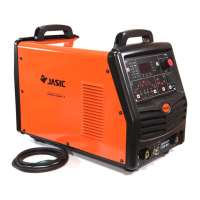
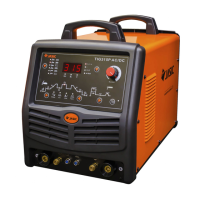
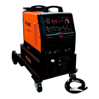
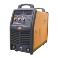
This document describes the AC.DC TIG-200/AC.DC TIG-250/AC.DC TIG-315 Inverter Series welding machines, which are designed with advanced inverter technology.
Function Description:
These welding machines are rectifiers that utilize high-frequency inverting technology. The core principle involves converting the 50/60Hz working current into direct current, then inverting it to a high frequency (e.g., above 100KHz). The voltage is subsequently reduced, and the current is commutated again to output a high-power direct current source using pulse-width modulation (PWM). This process significantly reduces the weight and volume of the main transformer while increasing efficiency by over 30%.
The AC.DC series welding machines are versatile, capable of both AC and DC argon arc welding. The "AC" position is used for welding aluminum materials, while the "DC" position is suitable for stainless steel, iron, copper, carbon steel, alloy steel, and other non-ferrous metals. A key feature is the double inverting technology, which generates a clear square-wave output. This results in a stronger arc, centralized heat, improved inverted clearing capability, a wide clearing range, and a stable arc even with small currents, leading to good welding performance.
The machines are equipped with a hand/foot transfer switch. In the "OFF" position, current is adjusted via a knob on the control panel. In the "ON" position, current is controlled by a foot switch, allowing for hands-free operation. The foot switch enables dynamic current adjustment during welding, increasing current for quick heating at the start or when feeding wires, and decreasing it for better weld formation. This enhances welding efficiency and quality while reducing difficulty. An optional foot impulse device can be purchased for impulse welding operations.
Important Technical Specifications (AC.DC TIG-200 / AC.DC TIG-250 / AC.DC TIG-315):
- Power Voltage:
- AC.DC TIG-200: Single-phase AC110V/220V ±15%
- AC.DC TIG-250, AC.DC TIG-315: Three-phase AC380V ±15%
- Power Frequency: 50/60 Hz for all models
- Rated Input Current:
- AC.DC TIG-200: 20.7 A
- AC.DC TIG-250: 9.6 A
- AC.DC TIG-315: 13.9 A
- Output Current Adjustment:
- AC.DC TIG-200: 20-200 A
- AC.DC TIG-250: 20-250 A
- AC.DC TIG-315: 20-315 A
- No-load Voltage:
- AC.DC TIG-200: 56 V
- AC.DC TIG-250, AC.DC TIG-315: 45 V
- Rated Operating Voltage:
- AC.DC TIG-200: 18 V
- AC.DC TIG-250: 20 V
- AC.DC TIG-315: 23 V
- Pre-flow: 0-2 S
- Duty Ratio: 20-80%
- Down-slope Time: 0-5 S
- Post Gas: 2-10 S
- Remote Control:
- AC.DC TIG-200: Non-available
- AC.DC TIG-250, AC.DC TIG-315: Available
- Arc Initiation: High frequency for all models
- Efficiency: 85% for all models
- Duty Cycle: 60% for all models
- Power Factor: 0.93 for all models
- Insulation Grade: B for all models
- Shell Protection Grade: IP21 for all models
- Weight: 20 kg for all models
- Outline Dimension: 710x400x660 mm for all models
- Maximum Welding Thickness: 27 mm for all models
- Frequency: 0.5-10 Hz
- Duty Ratio: 20-80%
- Valley Valve: 10-90%
Usage Features:
- Safety Warnings: Emphasizes electric shock prevention (grounding, insulation, avoiding contact with live parts), fume inhalation prevention (ventilation), arc radiation protection (protective clothing, masks), fire hazard prevention (no tinder), hot metal burn prevention, and noise protection (ear shields). Users are advised to seek professional help for malfunctions. An electricity leakage protection switch is mandatory.
- Control Panel:
- AC/DC Transfer Switch: Selects between AC (aluminum) and DC (stainless steel, iron, copper) welding modes.
- Hand/Foot Transfer Switch: Determines whether current is controlled by the panel knob ("OFF") or a foot switch ("ON").
- Pre-flow Time Adjustment Knob: Adjusts the delay before current turns on, ensuring argon gas reaches the welding position first.
- Current Adjustment Knob: Adjusts welding current (active only when hand/foot switch is "OFF").
- Duty Ratio Adjustment Knob: Controls the ratio of positive to negative current time during AC argon arc welding. Positive current (tungsten to workpiece) centralizes heat and is good for welding, while negative current (workpiece to tungsten) removes oxidized surface. Adjusting this knob balances welding quality and tungsten needle protection. Smaller duty ratios are recommended for higher currents (e.g., <30% for >200A), and larger duty ratios for smaller currents (e.g., >50% for <100A).
- Installation: Involves connecting the foot switch (if used), ensuring proper power cord connection to a voltage-matched distribution chamber, and verifying correct input voltage within the permitted range.
- AC Argon Arc Welding Application: Set AC/DC switch to "AC," turn on power, adjust argon gas flow, adjust positive/negative current time ratio based on oxidation, press the welding torch switch to activate the solenoid valve and high-frequency spark (purge gas for several seconds initially), set hand/foot switch as desired, adjust pre-flow, post-flow, and decay time, and maintain 2-4mm distance between tungsten electrode and workpiece for arc initiation.
- DC Argon Arc Welding Application: Set AC/DC switch to "DC," turn on power, adjust argon gas flow, and follow the same steps for arc initiation and parameter adjustment as AC welding.
Maintenance Features:
- General Maintenance: All maintenance must be performed with power disconnected and the plug pulled out.
- Dust Removal: Blow away dust with dry, clean compressed air regularly, especially daily in polluted environments. Use appropriate air pressure to protect small components.
- Circuit Inspection: Regularly check for correct and firm connections, especially plugs and components. Remove rust or oxide film with abrasive paper and reconnect if necessary.
- Moisture Prevention: Prevent water/vapor ingress. If moisture occurs, dry the machine and check insulation with a megohmmeter. The machine can only operate when everything is normal.
- Storage: If unused for extended periods, store in the original packing case in a dry environment.
- Pre-inspection Warning: Blindfold experience and incautious inspection can lead to problems. Bare parts inside the machine carry dangerous voltage when on, posing a shock hazard.
- Warranty: The warranty is void if the user inspects and repairs the welding cut power without permission.
- Environmental Requirements:
- Dry environment with air humidity not exceeding 90%.
- Ambient temperature between -10°C and 40°C.
- Prohibit water/rainwater permeation; avoid welding in sun or rain.
- Avoid welding in dusty or corrosive gas environments.
- Avoid welding in strong airflow.
- Safety Keys:
- Ventilation: Ensure good ventilation with at least 0.3m distance from surrounding objects, as the internal fan is crucial for cooling.
- Overload Protection: Observe maximum permissible load current and endurance ratio to prevent damage. Over-current shortens machine life.
- Over-voltage Protection: Adhere to specified power voltage ranges. The machine has voltage autocompensation, but exceeding allowable values can cause damage.
- Grounding: A grounding screw (marked with a sign) is present on the back. Use a cable of at least 6mm² for grounding to prevent static electricity and leakage accidents.
- Overheat Protection: The machine will automatically stop if the load endurance ratio is exceeded or overheating occurs, indicated by a yellow lamp. The cooling fan continues to run. Welding can resume when the red indicator extinguishes and temperature returns to normal.
Troubleshooting (Common Problems):
- Welded dots become black: Indicates ineffective protection and oxidation. Check argon gas bottle pressure (should be >0.5MPa), argon gas flow (recommend >3L/min), and for blocked gas circuits or low purity gas. Strong airflow can also degrade quality.
- Arc hard to start/easy to break: Check tungsten electrode quality (good discharge ability) and sharpness.
- Output current lower than rated value: May be due to deviant (lower) supplied voltage.
- Unsteady current: Can be caused by voltage changes in the electric network or interference from other electrical equipment.
- Serious burned tungsten electrode: Occurs if the duty ratio is too large, leading to prolonged electron emission and overheating.
- Oxidized film on aluminum workpiece not exposed: Check for wrong position selection, insufficient duty ratio adjustment, or damaged double-times invert MOSFET.
Troubleshooting (Specific Failure Phenomena for AC.DC TIG-200 / AC.DC TIG-250, AC.DC TIG-315):
- Power indicator off, fan not rotating, no welding output:
- Check power switch, input cable, and connections for damage or short circuits.
- For AC.DC TIG-200: May be wrongly connected to 380V (over-voltage protection active), unstable 220V supply, or continuous short-time power switch toggling. Check 24V relay on power board or loose cable between switch and power board.
- For AC.DC TIG-250/315: Check air switch, power network, thermal resistors on power supply board, or malfunction on power/base board (no DC537V output), or control panel auxiliary power supply failure.
- Power indicator on, fan not rotating/stops, no welding output:
- For AC.DC TIG-200: Check voltage between VH-07 inserter on MOS board and power board (should be ~DC308V). Check green indicator on MOS board auxiliary power supply. Check connecting wires.
- For AC.DC TIG-250/315: Check connecting wires or control circuit failure.
- Abnormal indicator off, "susurrus" sound, no arc starting:
- Check welding gun cable, grounding wire, anode output terminal, or gas-electricity output terminal connections.
- Check connection between primary wire of arc starting transformer and power supply board.
- Check discharging electrode for oxidation or distance.
- Check for damaged individual components of high-frequency arc starting circuit.
- For AC.DC TIG-200: Check for damaged manual argon welding transfer switch.
- Abnormal indicator on, no output:
- May be caused by over-current or over-heat protection (wait for indicator to extinguish).
- Inverter circuit failure: Unplug master transformer power terminal on MOS board and restart. If indicator remains on, check for damaged individual MOSFET on MOS board or voltage increasing transformer of high-frequency arc starting circuit. If indicator is off, check transformer on middle board (primary inductance, Q value) or double-times rectifier of middle board.
- Short circuit in feedback circuit.
- Oxidized film on aluminum workpiece not exposed: Wrong position selection, insufficient duty ratio adjustment, or damaged double-times invert MOSFET.
- Serious burned tungsten electrode: Duty ratio out of specification; reduce it.