EasyManua.ls Logo

Jasic TIG 200 P AC-DC User Manual

Jasic TIG 200 P AC-DC
2 pages
To Next Page IconTo Next Page
Page #1 background imageLoading...
Page #1 background image
PZB-43-C
1
CP3
1
CP4
D1
BA150E
D2
BA150E
K
磁阀
1
3
CON2
VH-03(2)
1
3
CON3
VH-03(2)
1
3
CON6
VH-03(2)
1
3
CON4
VH-03(2)
1
2
CON11
VH-02
1
2
CON13
VH-02
1
2
CON14
VH-02
1
2
3
4
CON1
VH-04
1
PCON1
1
PCON2
PM-32-I1
1
2
3
5
6
7
X1
VH-07(6)
1
2
X8
VH-02
1
3
X2
VH-03(2)
PNB-12-A
PDB-06-O
1
2
3
X6
VH-03
*
*
*
*
*
22:4
FMX32S
FMX32S
FMX32S
FMX32S
OUT+
OUT-
IN 1
IN 2
PNB-11-A
IN+
IN-
IN+
IN-
15:15 F? FLQ
1
2
3
X2
VH-03
OUT A
OUT B
1
3
CON1
VH-03(2)
OUT +
OUT -
1 2
4
3
弧器LI-201B
104/630V
472/3KV 472/3KV
AC220V IN
Current feedback
被釉电阻 50W/320R
被釉电阻 50W/320R
PKB-09-B
1
8
3
4
6
7
9
10
2
5
X1
VH-10
1
G
1
H
1
E
1
F
1
C
1
D
1
B
1
A
1
2
3
4
X2
VH-04
1
2
4
5
X3
VH-05(4)
A
B
C
D
E
F
G
H
Second driven
T?
20V
20V
20V
20V
20V
HF
HF Control
PH-10-D
Torch switch
1
2
3
XH-03
1
B
1
A
L2
2T/4T
1
2
3
4
Display meter
SW
Current control
REM Switch
TIG/MMA
REM Control
AC 220V
CP6
CP1CP2
CP4
CP5
20A220V
PH-84-E
地线
L N
地线
AC220VOUT
M?
FAN
M?
FAN
1
2
CON12VH-02
1
2
3
4
X4
VH-04
1
2
3
X9
VH-03
220V
Current check
Gas control
CP1
CP3
CP2
CP1
CP3
CP2
TIG200PACDC接线图
CP3
1
2
3
5
6
7
X3
VH-07(6)
1
2
3
5
6
7
CON8
VH-07(6)
1
2
3
4
6
7
9
10
CON9
VH-10(8)
1
2
3
4
6
7
9
10
CON10
VH-10(8)
1
2
3
4
X7
XH-04
DC310V
DC24V
RV6
103/3KV
RV5
472/3KV
1
2
X12
XH-02
1
2
3
4
5
X4
XH-05
1
2
X4
XH-02
1
2
X2
XH-02
1
2
3
X6
XH-03
1
2
3
4
X9
XH-04
1
2
X3
XH-02
1
2
X1
XH-02
1
2
3
X7
XH-03
1
2
3
X8
XH-03
1
2
3
4
X10
XH-04
Driven
1
2
3
4
X11
XH-04
1
2
X5
XH-02
SW
AC/DC
Frequency switch
LED1
Abnormal Indicator
1 2
SW-01
1 2
SW-01
1
2
X10
XH-02
PKB-31-D
Question and Answer IconNeed help?

Do you have a question about the Jasic TIG 200 P AC-DC and is the answer not in the manual?

Jasic TIG 200 P AC-DC Specifications

General IconGeneral
AC Frequency50/60Hz
Input PhaseSingle Phase
Protection ClassIP21S
Output Current Range (MMA)10-160A
Open Circuit Voltage70V
Efficiency85%
Power Factor0.7
Insulation ClassF
Duty Cycle60% at 200A
Pulse Frequency0.5-200Hz
Duty Cycle (TIG)60% at 200A

Summary

Power Input and User Controls

AC Power Input

Connects to the AC 220V power supply, including ground connection.

Operational Switches

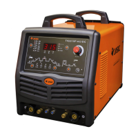
Includes Torch switch and REM switch for basic operation and remote control.

Parameter Adjustment Controls

Controls for setting frequency and current levels during welding.

Main Control and Processing Modules

PM-32-11 Main Processor

The central processing unit responsible for managing all welding functions and logic.

PZB-43-C Control Module

A key control module, likely involved in signal conditioning or power management.

PKB-31-D Interface Module

An interface or distribution module connecting various signals and components.

Power Drive and Ancillary Modules

PNB Series Power Driver Modules

PNB-12-A and PNB-11-A modules likely drive power output stages.

PKB-09-B Driven Module

Module related to driving or controlling specific outputs of the welder.

Igniter Unit (LI-201B)

Component responsible for initiating the arc during TIG welding.

Indicators and Feedback

Display Meter

Provides a visual readout of welding parameters or status.

Current Feedback and Indicators

Monitors welding current and provides status feedback or abnormal indication.

Related product manuals