63
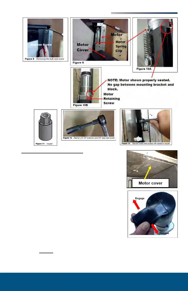
The system has been equipped with 3/4” hex override cou-
plers located on the drive component of the system. Due to
the size and weight of some rooms, assistance may be needed
to push the room in.
Use the following steps to mechanically operate the room.
1. Locate the ABS motor access cover for the slideout.
This cover will be located inside one of the storage
compartments under the slide room up at the top of the
compartment.
2. Remove (4) screws holding the panel to the top of the
compartment. Remove the cover.
3. Unplug the motor leads at the connector. Gray connec-
tor with red and black wires.
4. To release the motor brake you must depress the spring
lock lever, which then allows you to pivot the brake le-
ver, which in turn releases the brake. These parts are
located inside the rubber boot wire tied over the motor. You must manipulate these
parts removing the rubber boot.
These photos will help you gure out
how this works. The side-by-side photo (below) shows the spring lock lever and the
brake lever.