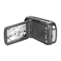
10) Flip the main board over and remove the two screws which hold the switch board in place.
Also, peel away the copper film from the bottom of the LCD. Note: Directly above the left
screw, the copper film is soldered to the main board. Try not to tear the copper from the main
board, but if it happens, it should be OK, the board will still operate. I think the copper film is
just for EMI noise emissions, not really critical if it get torn.
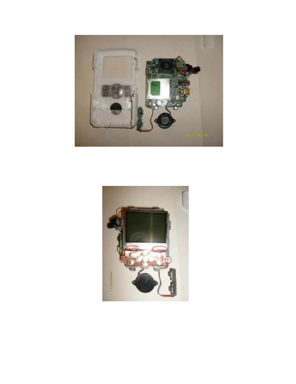
11) Now, pull up on the switch board and it should come
right out. Flip it over. You will see the connector. The pin numbers are marked on the header,
Pin 1 is on the lower left, pin 2 the lower right, pin 9 the top left, pin 10 the top right.

 Loading...