6
MAKING THE CONNECTIONS
A6000GTi SPEAKER
CONNECTIONS
The A6000GTi is a 2-channel amplifier
designed to drive subwoofers only.
The left and right input signals are
combined inside the amplifier to
provide a mono output signal, no
matter which output mode is selected.
The A6000GTi can be connected to
two independent speaker systems in
2-channel mode. It can be connected
to a combination of subwoofers
configured as a single load with its
channels bridged or connected in
parallel. Bridged channels will provide
high output voltage for driving loads
with a nominal impedance of 2 to 4
ohms. Connecting the channels in
parallel will provide the high current
necessary to drive loads of 1 to 2 ohms.
Included below are three application
diagrams that will help you plan
your A6000GTi installation. Figures 7
through 9 show how to configure the
JBL A6000GTi subwoofer amplifier for
bridged-mono, parallel-mono and
2-channel operation (see Setting Up
the GTi Amplifier).
IMPORTANT: If the nominal impedance
of the speaker system is close to 2
ohms, you may try both bridged and
parallel configurations to determine
which one performs better. Remember
to set the output mode switch to the
appropriate setting when changing
configurations.
NOTE: For simplicity, Figures 7 through
9 do not show power, remote and input
connections (see page 5).
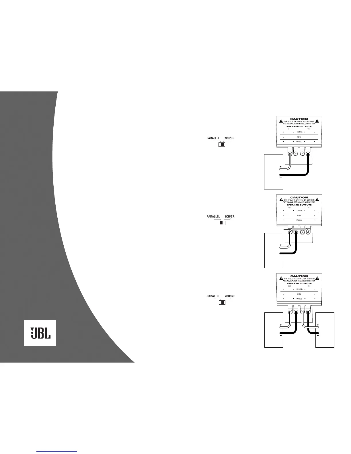
Figure 7. The JBL A6000GTi
subwoofer amplifier is set
to bridged mode to drive a
subwoofer system. Only use
this mode when the nominal
equivalent or total impedance
of the speaker system is
2 ohms or greater.
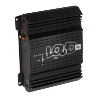
Figure 9. The JBL A6000GTi
subwoofer amplifier is set
to 2-channel mode to drive
a pair of subwoofers or
subwoofer systems with
nominal equivalent or total
impedances of 2 to 4 ohms.
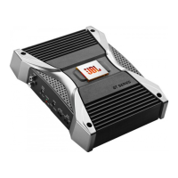
Figure 8. The JBL A6000GTi
subwoofer amplifier is set
to parallel mode to drive a
subwoofer system. Only
use this mode when the
nominal equivalent or total
impedance of the speaker
system is less than 2 ohms.
NOTE: A jumper is added
between the + terminals.